AXI GPIO key control LED
In the above, the interaction between PS and PL is realized through EMIO, and the main connection mode between PS and PL is a group of AXI interfaces. As a bridge between ZYNQ PS and PL, AXI interconnection interface can make them work together to form a complete and highly integrated system.
brief introduction
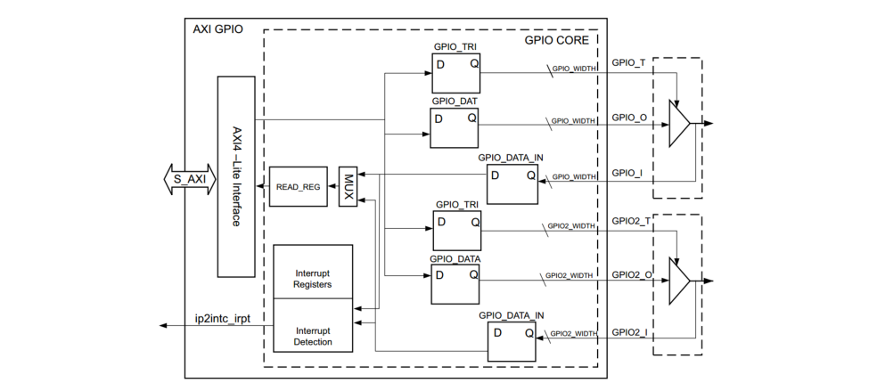
The AXI GPIO IP core provides a common input / output interface for the AXI interface. Unlike the PS side GPIO, AXI GPIO is a soft core (Soft IP), that is, the ZYNQ chip does not have such a hardware circuit at the factory, but a functional module realized by the user by configuring the logic resources at the PL side. The PS GPIO is a hard core (Hard IP), which is a functional circuit implemented in silicon chip during production. AXI GPIO can be configured as single channel or dual channel, and the bit width of each channel can be set separately. In addition, by opening or closing the three state buffer, the port of AXI GPIO can also be dynamically configured as an input or output interface. The block diagram of its top-level module is as follows:

As can be seen from the above figure, a 32-bit axi4 Lite slave interface is implemented on the left side of the module, which is used for the host to access the registers of each channel in AXI GPIO. When the input signal of the right interface changes, the module can also generate an interrupt signal to the host. However, the interrupt control function of the module can be enabled only when "enable interrupt" is selected when configuring the IP core.
Introduction to Block Design

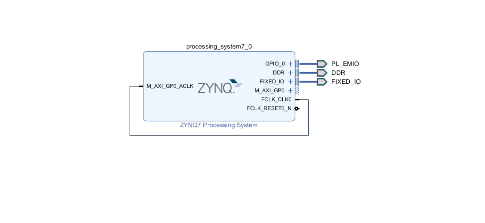
Some interface signals in zynq7 processing system are used for PS to communicate with PL terminal using AXI interface.
- M_AXI_GP0 is a general purpose Axi interface, which contains a set of signals. The initial letter M indicates that PS is the master and the peripheral in PL is the slave And m on the left_ AXI_ GP0_ Aclk is the global clock signal of this interface. It is an input signal, M_ AXI_ All signals of the Gp0 interface are sampled at the rising edge of the global clock.
- FCLK_CLK0 is the clock signal output by PS, which will be used as the clock source of PL external module. This clock is generated by the IO PLL in the PS, and the frequency range can be from 0.1 to 250MHz. When configuring the ZYNQ7 PS, the clock defaults to 50MHz.
- FCLK_RESET0_N is the global reset signal output from PS to PL, and the low level is valid.
- IRQ_F2P[0:0] is an interrupt signal output from PL to PS.
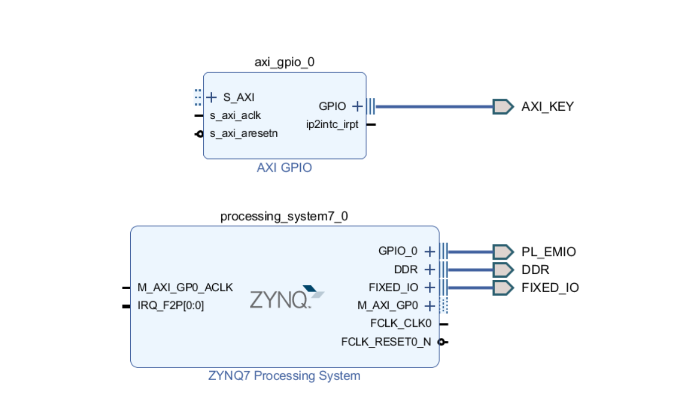
Add the AXI GPIO IP core of PL end in Block Design and configure it (this paper wants to realize the PL end key to control the PS end LED, select the data bit width as 1 bit), and check the interrupt.

Perform the Run Connection Automation operation.

At this time, Vivado automatically adds two IP cores: AXI Interconnect and processor system reset.
- The AXI Interconnect IP core is used to connect one (or more) AXI memory mapped master devices to one (or more) memory mapped slave devices. Here we explain the term Interconnect: an Interconnect is actually a switch that manages and directs the communication between the connected AXI interfaces. The two groups of orange highlighted signal lines in figure 5.3.8 show that in this design, AXI interconnection realizes one-to-one connection from the master device (ZYNQ7 PS) to the slave device (AXI GPIO). It can also implement one to many, many to one, and many to many AXI interface connections.
- The processor system reset IP core provides reset signals for the entire processor system. It will process various reset conditions at the input and generate corresponding reset signals at the output. Processor system reset receives asynchronous reset signal fclk output by ZYNQ7 PS_ RESET0_ N. Then a synchronization to pl clock source fclk is generated_ Reset signal of CLK0_ Aresetn, used to reset all peripheral modules at the PL end.
The clock interfaces of all peripheral modules at PL end are connected to the clock signal fclk output by ZYNQ7 PS_ On CLK0. It should be noted that the clock is also connected to PS terminal M_AXI_GP0_ACLK port, as the global clock signal of AXI GP interface. Connect the interrupt of AXI GPIO IP with the interrupt of ZYNQ7 Processing System.
Because the AXI GPIO button interrupt and the emo button are almost the same. There is not much introduction here. The author also completes the program experiment according to the official Example and EMIO key interrupt.
Example:
#include "stdio.h"
#include "xscugic.h"
#include "xgpiops.h"
#include "xgpio.h"
#include "xparameters.h"
#include "sleep.h"
#include "xil_exception.h"


#define AXI_GPIO_DEVICE_ID 	XPAR_GPIO_0_DEVICE_ID
#define PS_GPIO_DEVICE_ID  	XPAR_XGPIOPS_0_DEVICE_ID
#define SCUGIC_DEVICE_ID	XPAR_SCUGIC_0_DEVICE_ID
#define AXI_GPIO_INTR_ID  	XPAR_FABRIC_GPIO_0_VEC_ID

#define PS_LED0_MIO0			0
#define KEY_CHANNEL             1
#define KEY_MASK                XGPIO_IR_CH1_MASK

int PerInstInit(XGpioPs *PsGpioInst,XGpio *AxiGpioInst,XScuGic *AxiIntr,u16 PsGpioDeviceId,u16 AxiGpioDeviceId,u16 ScugicDeviceId);
int SetupInterruptSystem(XScuGic *AxiIntr,XGpio *AxiGpio,u16 AxiGpioIntrId);
void AxiGpioHandler(void *CallBackRef);


int led_value = 1;
XGpioPs PsGpio;
XGpio AxiGpio;
XScuGic AxiIntr;
int main(void)
{
	int status;

	status = PerInstInit(&PsGpio, &AxiGpio, &AxiIntr, PS_GPIO_DEVICE_ID, AXI_GPIO_DEVICE_ID, SCUGIC_DEVICE_ID);
	if(status != XST_SUCCESS)
	{
		printf("Initialize Failure!\n");
		return XST_FAILURE;
	}
	XGpioPs_SetDirectionPin(&PsGpio,PS_LED0_MIO0, 0x1);
	XGpioPs_SetOutputEnablePin(&PsGpio,PS_LED0_MIO0,0x1);
	XGpioPs_WritePin(&PsGpio,PS_LED0_MIO0,led_value);

	XGpio_SetDataDirection(&AxiGpio, KEY_CHANNEL, 0x1);
	SetupInterruptSystem(&AxiIntr,&AxiGpio,AXI_GPIO_INTR_ID);

	while(1);
	return XST_SUCCESS;

}


int PerInstInit(XGpioPs *PsGpioInst,XGpio *AxiGpioInst,XScuGic *AxiIntr,u16 PsGpioDeviceId,u16 AxiGpioDeviceId,u16 ScugicDeviceId)
{
	int status;
	XScuGic_Config *ScugicConfigPtr;
	XGpioPs_Config *PsGpioConfigPtr;
	XGpio_Config *AxiGpioConfigPtr;
	PsGpioConfigPtr  = XGpioPs_LookupConfig(PsGpioDeviceId);
	if(NULL == PsGpioConfigPtr)
		return XST_FAILURE;
	AxiGpioConfigPtr = XGpio_LookupConfig(AxiGpioDeviceId);
	if(NULL == AxiGpioConfigPtr)
		return XST_FAILURE;
	ScugicConfigPtr  = XScuGic_LookupConfig(ScugicDeviceId);
	if(NULL == ScugicConfigPtr)
		return XST_FAILURE;
	status = XGpioPs_CfgInitialize(PsGpioInst, PsGpioConfigPtr, PsGpioConfigPtr->BaseAddr);
	if(status != XST_SUCCESS)
		return XST_FAILURE;
	status = XGpio_CfgInitialize(AxiGpioInst,AxiGpioConfigPtr,AxiGpioConfigPtr->BaseAddress);
	if(status != XST_SUCCESS)
		return XST_FAILURE;
	status = XScuGic_CfgInitialize(AxiIntr, ScugicConfigPtr, ScugicConfigPtr->CpuBaseAddress);
	if(status != XST_SUCCESS)
		return XST_FAILURE;
	return XST_SUCCESS;
}


int SetupInterruptSystem(XScuGic *AxiIntr,XGpio *AxiGpio,u16 AxiGpioIntrId)
{
	int status;
//	1.
	Xil_ExceptionInit();
	Xil_ExceptionEnableMask(XIL_EXCEPTION_IRQ);
	Xil_ExceptionRegisterHandler(XIL_EXCEPTION_ID_INT,
			(Xil_ExceptionHandler)XScuGic_InterruptHandler,	AxiIntr);
//	2.
	status = XScuGic_Connect(AxiIntr, AxiGpioIntrId, AxiGpioHandler, (void*)AxiGpio);
	if(status != XST_SUCCESS)
		return XST_FAILURE;
//	3.
	XScuGic_Enable(AxiIntr, AxiGpioIntrId);
//  4.
	XGpio_InterruptEnable(AxiGpio,KEY_MASK);
	XGpio_InterruptGlobalEnable(AxiGpio);
	XScuGic_SetPriorityTriggerType(AxiIntr, AxiGpioIntrId, 0,1);
	return XST_SUCCESS;
}


void AxiGpioHandler(void *CallBackRef)
{
	int key_value = 1;
	XGpio *GpioPtr = (XGpio *)CallBackRef;
	printf("Interrupt Detected!\n");
	XGpio_InterruptDisable(GpioPtr, KEY_MASK);
	key_value = XGpio_DiscreteRead(GpioPtr, KEY_CHANNEL);
	if(key_value == 0)
	{
		led_value = ~led_value;
		XGpioPs_WritePin(&PsGpio,PS_LED0_MIO0,led_value);
	}
	usleep(200000);
	XGpio_InterruptClear(GpioPtr, KEY_MASK);
	XGpio_InterruptEnable(GpioPtr, KEY_MASK);

}
Since the author has not learned MCU or ARM before, the author has gradually raised questions here. Record it here first. After seeing if there is any way to find out, I also welcome netizens to give me the answers I want, and we can make progress together.
Q: **s32 XScuGic_Connect(XScuGic InstancePtr, u32 Int_Id,Xil_InterruptHandler Handler, void CallBackRef)
What is the working mechanism of this function, that is, how the interrupt returns to the original program in the operating system. How are Handler and CallBackRef related?
Q: **void XScuGic_SetPriorityTriggerType(XScuGic *InstancePtr, u32 Int_Id,u8 Priority, u8 Trigger) * * in this experiment, AXI interrupt belongs to shared peripheral interrupt (SPI),
High level sensitive The key connection mode in the hardware circuit is as follows:

The English explanation is high-level sensitivity (it doesn't seem to be what I think. An interrupt will be generated as long as the detected IO port level is high). I actually observe that an interrupt will be generated only when I press the key (IO level from high to low).
Data : 2022-1-5
Author : QImua
City : Wuxi