ZYNQ AC7020
I brief introduction
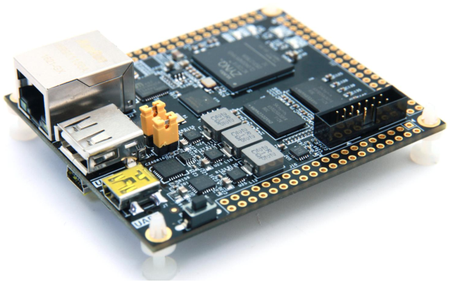
No matter which development board to learn, it starts from lighting the light, just like the software originated from hello world. Here I use the AC7020 development board of 7000 series. Today I will talk about the GPIO control of 7000 series
Note that GPIO here is divided into three categories: GPIOMIO/EMIO/AXI_GPIO
II MIO and EMIO/AXI_GPIO
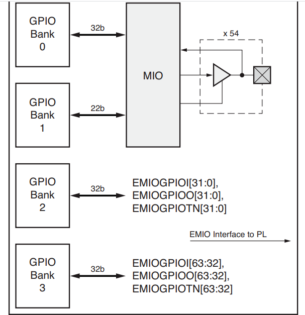
The following figure shows the structure of EMIO and MIO
- There are 54 MIO s in total (0-53),
- The total number of emios is 64 (54-117)
MIO is distributed in BANK0 and BANK1, while EMIO is distributed in BANK2 and BANK3. The total number is 118 gpios, all of which belong to PS resources
Bank0:MI0[31:0]
Bank1:MI0[53:32]
Bank2:EMI0[31:0]
Bank3:EMI0[63:32]
1.MIO
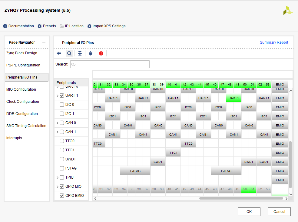
First, the pin of MIO on zynq is fixed, as shown in the figure below. It can be configured in vivado software and can be used as USB, SD card, UART and other peripherals.
Note: MIO does not occupy the resources of PL and does not require pin constraint configuration. It can be loaded and used after power on
2.EMIO
EMIO is extended through the PL part, so when using EMIO, pins need to be allocated in the constraint file. Therefore, when designing the program of EMIO, it is necessary to generate the bit file of PL part and burn it into FPGA
Note: EMIO occupies PL resources
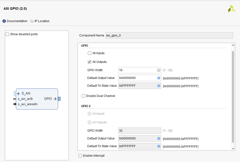
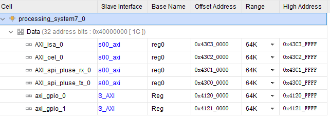
3.AXI_GPIO
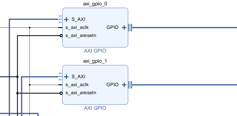
AXI_GPIO is connected to GPIO on PS through Axi bus_ GPIO is equivalent to the IP core of GPIO. When we call, we occupy the address space of the corresponding Axi bus, as shown in the figure below. The occupied addresses are 0x41200000 and 0x4121000
be careful
Both EMIO and IP modes need to bind pins in vivado
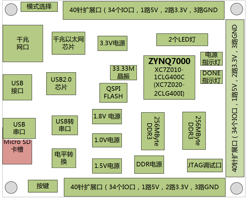
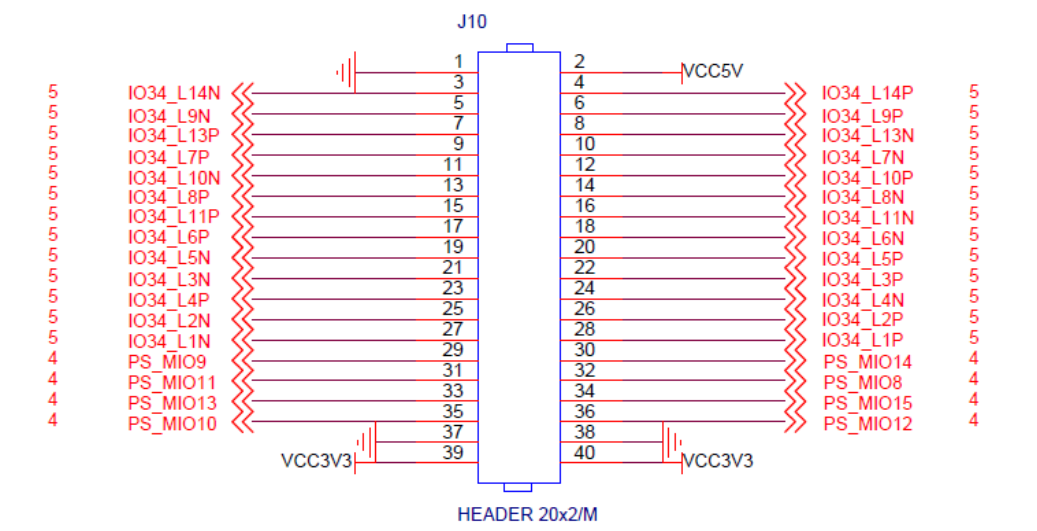
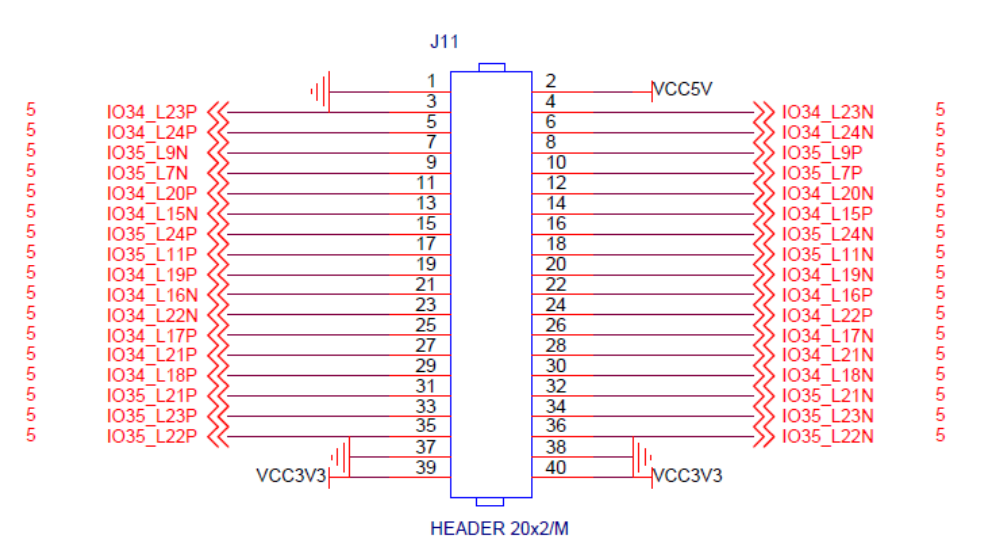
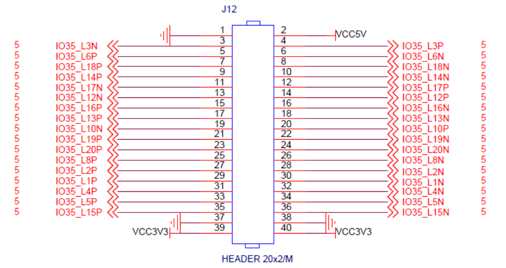
III Development board IO port
Let's take another look at the IO ports available to users of AC7020. There are 3 groups of 34 IOS, with a total of 112
- 94 IOS of PL
- 8 IOS of PS
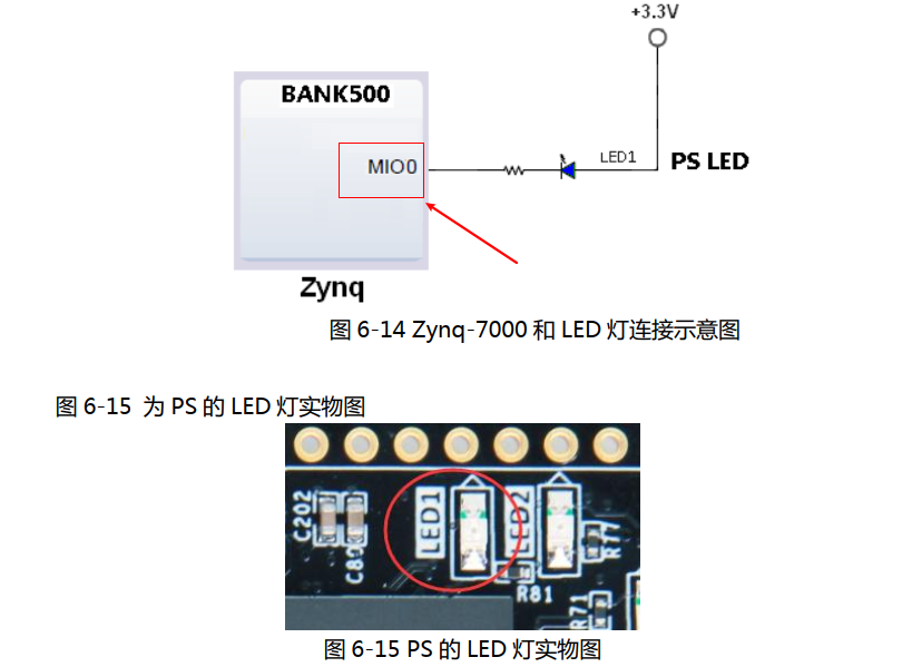
The experiment in this chapter is to light up the LED on the development board. First look at the LED circuit
PS LED received MIO0
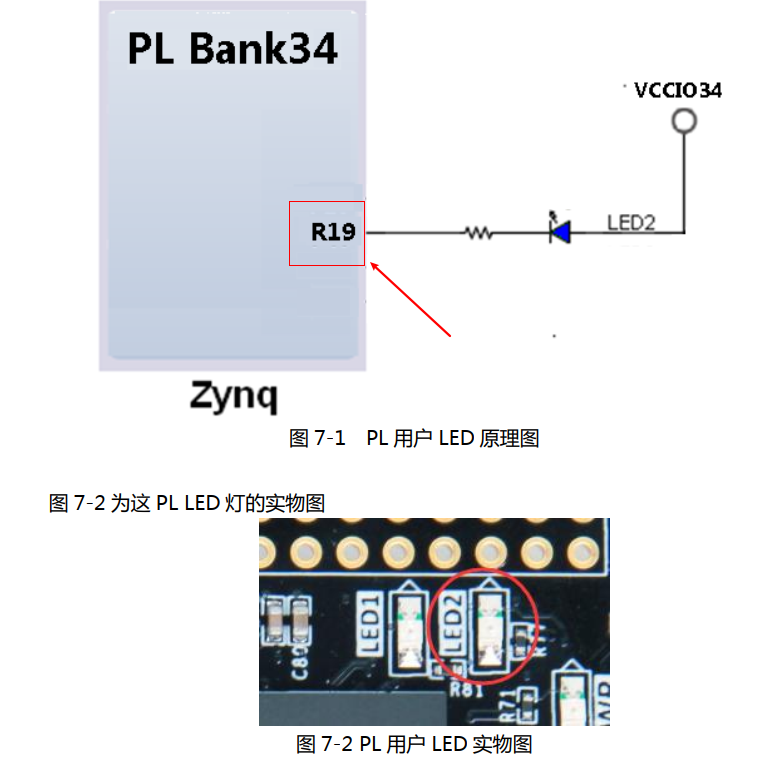
The LED at PL end is connected to R19 (IO_0_34)
IV Bare metal development Lighting
Here, you can directly use xgpiops to control IO H library function. Note that the PL end needs pin constraints
1. Code part
#include <stdio.h>
#include "xil_printf.h"
#include "xgpiops.h"
#include "sleep.h"

//There are 54 MIO s, numbered from 0 to 53, so 54 is the first EMIO port
//This macro definition corresponds to the number of Mio LEDs
#Define LED1 0 / / power indicator
#define led2    54  //
XGpioPs gpio_mio;

int MIO_Config(void)
{
	XGpioPs_Config *gpioPtr;
	int status;
	//Each peripheral has an ID, and the ID of GPIO is in xpparameters Defined in H
	gpioPtr = XGpioPs_LookupConfig(XPAR_PS7_GPIO_0_DEVICE_ID);
	status = XGpioPs_CfgInitialize(&gpio_mio, gpioPtr, gpioPtr->BaseAddr);
	if(status != XST_SUCCESS)
	{
		xil_printf("can't config gpio\n\r");
		return XST_FAILURE;
	}

	//Configure led1 to output mode
	XGpioPs_SetDirectionPin(&gpio_mio, led1, 1);
	XGpioPs_SetDirectionPin(&gpio_mio, led2, 1);
	//Output enable
	XGpioPs_SetOutputEnablePin(&gpio_mio, led1, 1);
	XGpioPs_SetOutputEnablePin(&gpio_mio, led2, 1);

	//Configure input mode
	//XGpioPs_SetDirectionPin(&gpio_mio, key, 0);

	return XST_SUCCESS;
}

//Write gpio
void MIO_LED(int led, int status)
{
	//Write the output value of GPIO
	XGpioPs_WritePin(&gpio_mio, led, status);
}

//Read gpio
int MIO_KEY( int key1 )
{
	//Read the value of GPIO
	int value = XGpioPs_ReadPin(&gpio_mio, key1);
	return value;
}


int main()
{
    print("====led test====\n\r");
    MIO_Config();
    while(1)
    {
    	MIO_LED(led1, 0);
    	sleep(1);
    	MIO_LED(led1, 1);
    	sleep(1);
    	MIO_LED(led2, 0);
    	sleep(1);
    	MIO_LED(led2, 1);
    	sleep(1);
    }

    return 0;
}
2. Test
First add fsbl with SDK to generate fsbl ELF file, then vivado project generates bit file, and then compiles the above code to generate led Elf files are combined into boot Bin file, put it on the sd card, select the sd card to start, and you can see LED1 and LED2 blink alternately
V GPIO control of linux system
In the vivado project, 16 pins are restricted for GPIO0 and 16 pins are restricted for GPIO1. Configure the linux system startup file and enter the system. We can see three GPIO chips 8748906 in the / sys/class/gpio directory
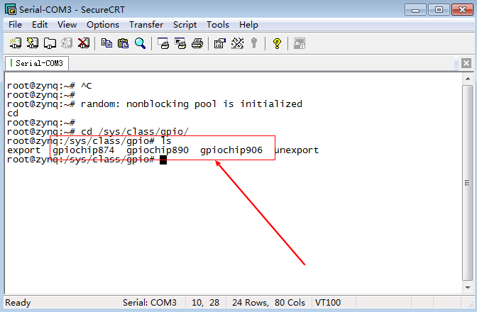
How to correspond? Firstly, the gpio number can represent 1024 at most. As mentioned earlier, there are 54 MIO s on the PS side and 118 EMIO64 in total
- PS end GPIO 906-1024
- AX_GPIO0 corresponds to 16 constraint pins 890-905
- AX_GPIO1 corresponds to 16 constraint pins 874-889
Therefore, the control number corresponding to MIO0 is GPIO906 and MIO1 is 907. The first GPIO number of EMIO constraint is GPIO890 and the first is GPIO891
Note: EMIO can restrict up to 64, ax_gpio0 32, ax_gpio1 32
The control procedures are not explained here. After knowing the gpio number, the method of controlling gpio in the linux layer should be the same, as explained in the previous article.
Vi summary
Here is only a rough description of the control of ZYNQ7000 series GPIO under bare metal and ubuntu systems. The specific operation process is not necessary to explain