Analysis of ESP32 GPIO external interrupt Principle & GPIO external interrupt practice
Reading suggestions:
it has a certain Cortex-m architecture and Xtensa ® 32-bit LX6 architecture knowledge base.
software environment
- VSCODE-ESP32-IDF4.3 plug in version
- LVGL project for ESP32
hardware environment
- ESP32-D2WD
External interrupt principle
ESP32-GPIO
ESP32 has 34 GPIO pins in total. By configuring the corresponding registers, different functions can be assigned to these pins, including the following types of GPIO: GPIO with digital function only, GPIO with analog function, GPIO with capacitive touch function, etc.
GPIO with analog function and GPIO with capacitive touch function can be configured as digital GPIO. Most gpios with digital functions can be configured as internal pull-up / pull-down, or set to high resistance. When configured as input, the input value can be obtained by reading the register. The input pin can also be set to generate CPU interrupt through edge trigger or level trigger. Most digital IO pins are bidirectional, non inverting and three state, including input and output buffers with three state control. These pins can be reused for other functions, such as SDIO, UART, SPI, etc. (refer to appendix IO_MUX for more information). When the chip operates with low power consumption, GPIO can be set to hold state.
ESP32-INTERRUPT
the ESP32 interrupt matrix assigns any external interrupt source to any external interrupt of each CPU separately. This provides strong flexibility and can adapt to different application requirements. This is different from the external interrupt of Cortex-m architecture. It is not set through the NVIC vector table, but the interrupt matrix.
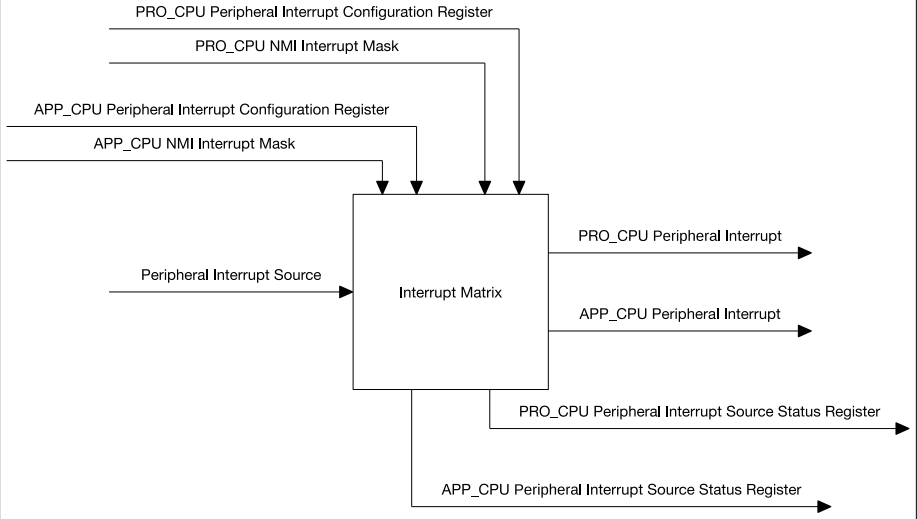 Figure 1: interrupt matrix structure
Main characteristics
• accept 71 external interrupt sources as inputs
• generate * * 26 external interrupts (52 in total) * * for two CPU s respectively as output
• NMI type interrupts that mask the CPU
• query the current interrupt status of external interrupt source
It is worth noting that there are two concepts here: external interrupt source and external interrupt of CPU, which is the core of understanding ESP32 interrupt.
ESP32 external interrupt source
ESP32 has a total of 71 external interrupt sources. Figure 2 lists all external interrupt sources. 67 of the 71 external interrupt sources in ESP32 can be allocated to two CPUs. The remaining 4 external interrupt sources can only be allocated to specific CPUs, 2 for each CPU. GPIO_INTERRUPT_PRO and GPIO_INTERRUPT_PRO_NMI can only assign PRO_CPU,GPIO_INTERRUPT_APP and GPIO_INTERRUPT_APP_NMI can only be assigned to APP_CPU. Therefore, PRO_CPU and app_ Each CPU can be allocated to 69 external interrupt sources.
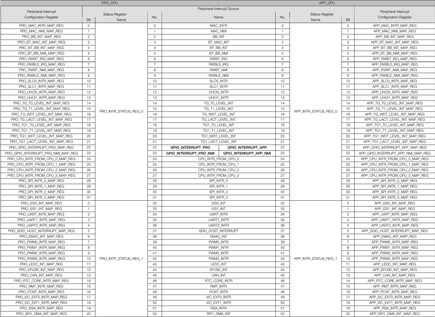 Figure 2: external interrupt source
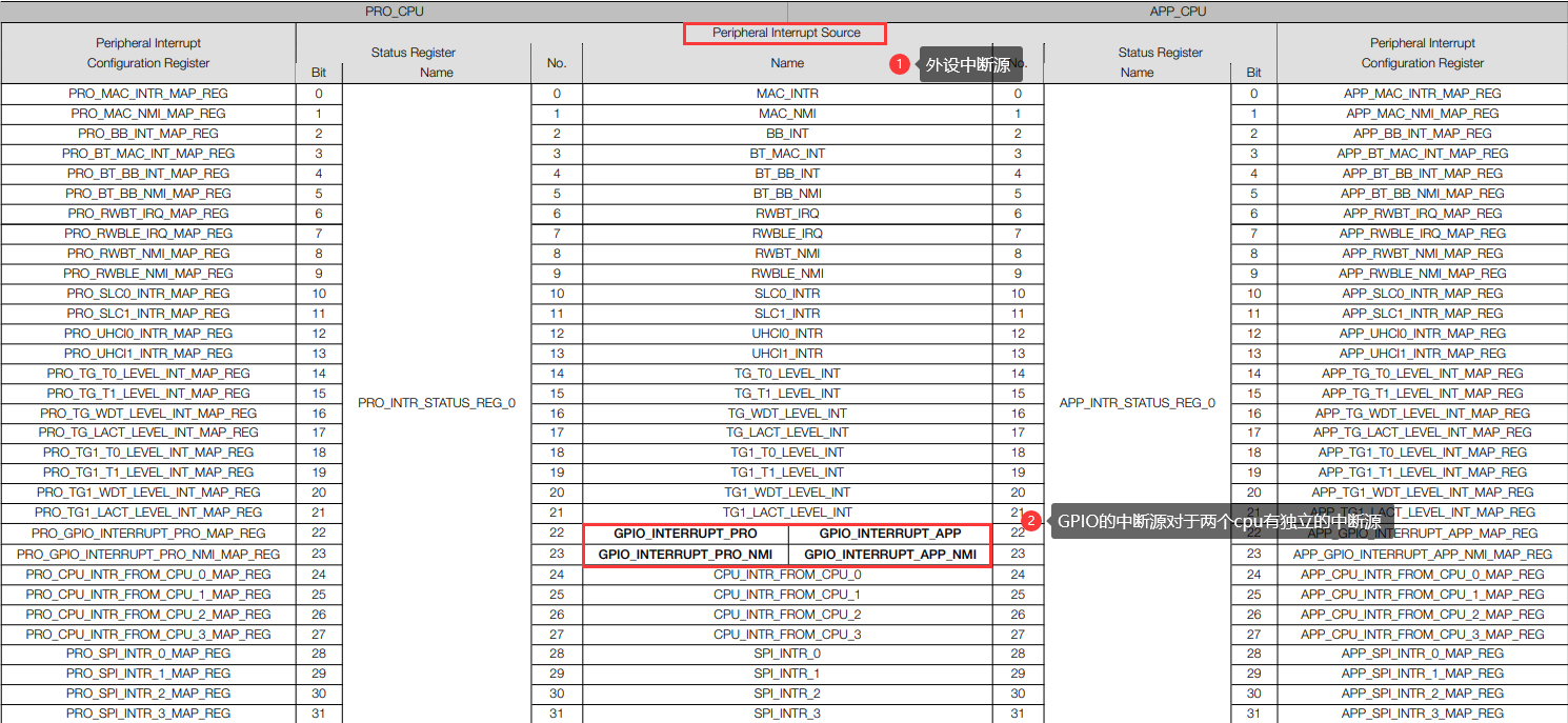 Figure 3: external GPIO interrupt source
External interrupt of ESP32-CPU
The two CPUs (PRO_CPU and APP_CPU) each have 32 interrupts, of which 26 are external interrupts. Figure 3 lists all the for each CPU
Interrupt.
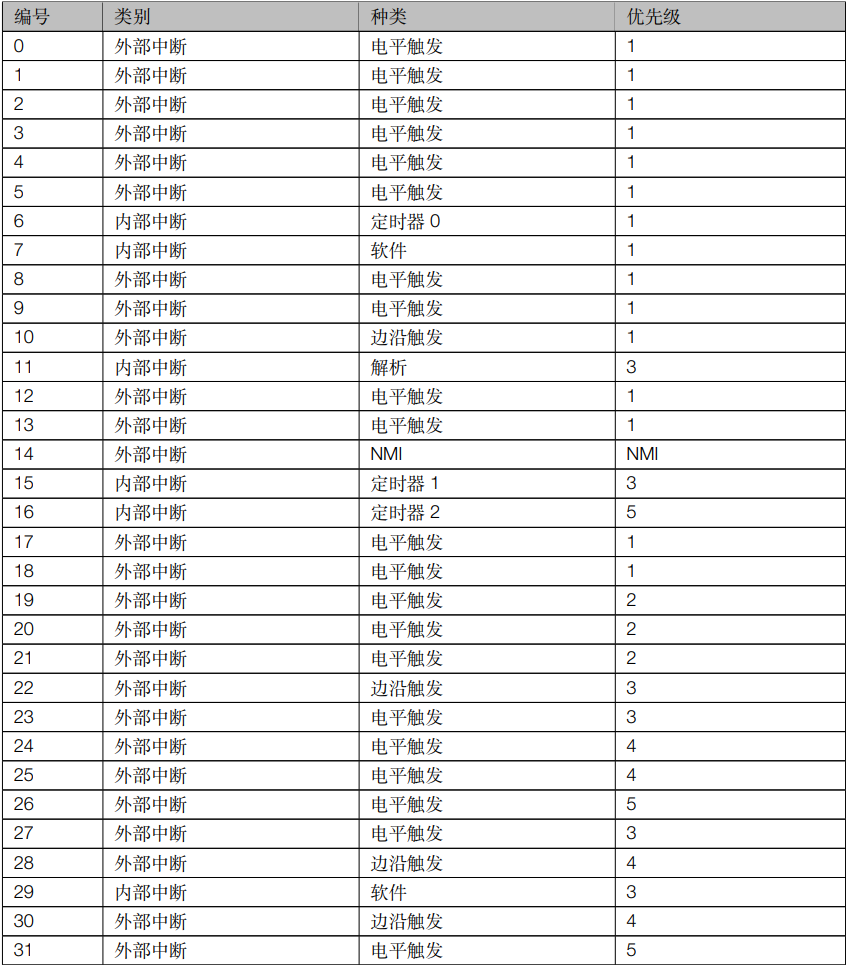 Figure 4: external interrupt of CPU
###External interrupt of ESP32-CPU external interrupt source the interrupt of each peripheral corresponds to an interrupt source, and each interrupt source corresponds to an interrupt source redirection register, as shown in Figure 3, * * GPIO_INTERRUPT_PRO * * interrupt source corresponds to * * PRO_GPIO_INTERRUPT_PRO_MAP_REG * * register can be mapped to the corresponding * * CPU external interrupt * * by setting this register, as shown in Figure 4. Whenever an interrupt occurs, interrupt processing and service can be realized through the callback function corresponding to * * CPU external interrupt * *. It is worth noting that an external interrupt of the CPU can be triggered by multiple interrupt sources, as long as the corresponding external interrupt number is written in the corresponding register. (each register * * PRO_Xn_MAP_REG** (**APP_Xn_MAP_REG * *) is configured with the same * * interrupt * * number. These peripheral interrupts will trigger * * CPU Interrupt_P * *).
Figure 4: external interrupt of CPU
###External interrupt of ESP32-CPU external interrupt source the interrupt of each peripheral corresponds to an interrupt source, and each interrupt source corresponds to an interrupt source redirection register, as shown in Figure 3, * * GPIO_INTERRUPT_PRO * * interrupt source corresponds to * * PRO_GPIO_INTERRUPT_PRO_MAP_REG * * register can be mapped to the corresponding * * CPU external interrupt * * by setting this register, as shown in Figure 4. Whenever an interrupt occurs, interrupt processing and service can be realized through the callback function corresponding to * * CPU external interrupt * *. It is worth noting that an external interrupt of the CPU can be triggered by multiple interrupt sources, as long as the corresponding external interrupt number is written in the corresponding register. (each register * * PRO_Xn_MAP_REG** (**APP_Xn_MAP_REG * *) is configured with the same * * interrupt * * number. These peripheral interrupts will trigger * * CPU Interrupt_P * *).
External interruption practice
- Configure GPIO first
ESP-IDF provides a structure to facilitate its initialization. The structure is as follows:
typedef struct {
    uint64_t pin_bit_mask;          /*!< GPIO pin: set with bit mask, each bit maps to a GPIO */
    gpio_mode_t mode;               /*!< GPIO mode: set input/output mode                     */
    gpio_pullup_t pull_up_en;       /*!< GPIO pull-up                                         */
    gpio_pulldown_t pull_down_en;   /*!< GPIO pull-down                                       */
    gpio_int_type_t intr_type;      /*!< GPIO interrupt type                                  */
} gpio_config_t;
the five members in this structure need to be initialized. The first one can start the GPIO of the corresponding number by setting the corresponding bit, and the rest are the mode setting and interrupt management members.
An example of initialization is shown below
#define GPIO(n)  (1ULL<<n)
#define EXTI_Num 0

 	gpio_config_t EXTI_config;
    EXTI_config.pin_bit_mask=GPIO(EXTI_Num);          /*!< GPIO pin: set with bit mask, each bit maps to a GPIO */
    EXTI_config.mode=GPIO_MODE_INPUT;         /*!< GPIO mode: set input/output mode*/
    EXTI_config.pull_up_en = 1;              /*!< GPIO pull-up*/
    EXTI_config.pull_down_en = 0;
    EXTI_config.intr_type=GPIO_INTR_NEGEDGE;    /*!< GPIO interrupt type*/
in this example, the macro definition #define GPIO (n) (1ull < < n) is used to set the bit corresponding to GPIO. Here, GPIO0 is set. Because the mode is an external interrupt, it is set as the input mode. At the same time, because it is triggered by low level, the IO port needs to be pulled up first, so exti is enabled here_ config.pull_ up_ en = 1; Pull it up. The last one is the setting of interrupt mode. The official gives a total of 6 interrupt modes, as follows.
typedef enum {
    GPIO_INTR_DISABLE = 0,     /*!< Disable GPIO interrupt                             */
    GPIO_INTR_POSEDGE = 1,     /*!< GPIO interrupt type : rising edge                  */
    GPIO_INTR_NEGEDGE = 2,     /*!< GPIO interrupt type : falling edge                 */
    GPIO_INTR_ANYEDGE = 3,     /*!< GPIO interrupt type : both rising and falling edge */
    GPIO_INTR_LOW_LEVEL = 4,   /*!< GPIO interrupt type : input low level trigger      */
    GPIO_INTR_HIGH_LEVEL = 5,  /*!< GPIO interrupt type : input high level trigger     */
    GPIO_INTR_MAX,
} gpio_int_type_t;
from top to bottom are non enable interrupt, upper and lower edge trigger interrupt and high and low level trigger interrupt respectively. Here, the falling edge trigger interrupt is used.
finally through gpio_config function to import the settings of the structure into the corresponding register.
gpio_config(&EXTI_config);
The next step is to set the corresponding interrupt.
first turn on the GPIO interrupt. Note that this function does not need to be used once for each GPIO interrupt, but turns on the interrupt of the whole GPIO and registers the GPIO interrupt with the currently running core, that is, the interrupt processing function runs in which core you call this function. The functions are as follows:
gpio_install_isr_service(ESP_INTR_FLAG_LEVEL3);
ESP_INTR_FLAG_LEVEL3 is also a macro definition, which specifies the priority of this interrupt. As mentioned above, all interrupt priorities are defined as follows:
/** @brief Interrupt allocation flags
 *
 * These flags can be used to specify which interrupt qualities the
 * code calling esp_intr_alloc* needs.
 *
 */

//Keep the LEVELx values as they are here; they match up with (1<<level)
#define ESP_INTR_FLAG_LEVEL1        (1<<1)  ///< Accept a Level 1 interrupt vector (lowest priority)
#define ESP_INTR_FLAG_LEVEL2        (1<<2)  ///< Accept a Level 2 interrupt vector
#define ESP_INTR_FLAG_LEVEL3        (1<<3)  ///< Accept a Level 3 interrupt vector
#define ESP_INTR_FLAG_LEVEL4        (1<<4)  ///< Accept a Level 4 interrupt vector
#define ESP_INTR_FLAG_LEVEL5        (1<<5)  ///< Accept a Level 5 interrupt vector
#define ESP_INTR_FLAG_LEVEL6        (1<<6)  ///< Accept a Level 6 interrupt vector
#define ESP_INTR_FLAG_NMI           (1<<7)  ///< Accept a Level 7 interrupt vector (highest priority)
#define ESP_INTR_FLAG_SHARED        (1<<8)  ///< Interrupt can be shared between ISRs
#define ESP_INTR_FLAG_EDGE          (1<<9)  ///< Edge-triggered interrupt
#define ESP_INTR_FLAG_IRAM          (1<<10) ///< ISR can be called if cache is disabled
#define ESP_INTR_FLAG_INTRDISABLED  (1<<11) ///< Return with this interrupt disabled

#define ESP_INTR_FLAG_LOWMED    (ESP_INTR_FLAG_LEVEL1|ESP_INTR_FLAG_LEVEL2|ESP_INTR_FLAG_LEVEL3) ///< Low and medium prio interrupts. These can be handled in C.
#define ESP_INTR_FLAG_HIGH      (ESP_INTR_FLAG_LEVEL4|ESP_INTR_FLAG_LEVEL5|ESP_INTR_FLAG_LEVEL6|ESP_INTR_FLAG_NMI) ///< High level interrupts. Need to be handled in assembly.

#define ESP_INTR_FLAG_LEVELMASK (ESP_INTR_FLAG_LEVEL1|ESP_INTR_FLAG_LEVEL2|ESP_INTR_FLAG_LEVEL3| \
                                 ESP_INTR_FLAG_LEVEL4|ESP_INTR_FLAG_LEVEL5|ESP_INTR_FLAG_LEVEL6| \
                                 ESP_INTR_FLAG_NMI) ///< Mask for all level flags
Finally, register the interrupt callback function to start the interrupt:
gpio_isr_handler_add(EXTI_Num,EXIT_Handelr,NULL);
Here, an external interrupt is initialized.