1, Working environment
Operating system: Win10
Development environment: Matlab 2019b (camera driver package required)
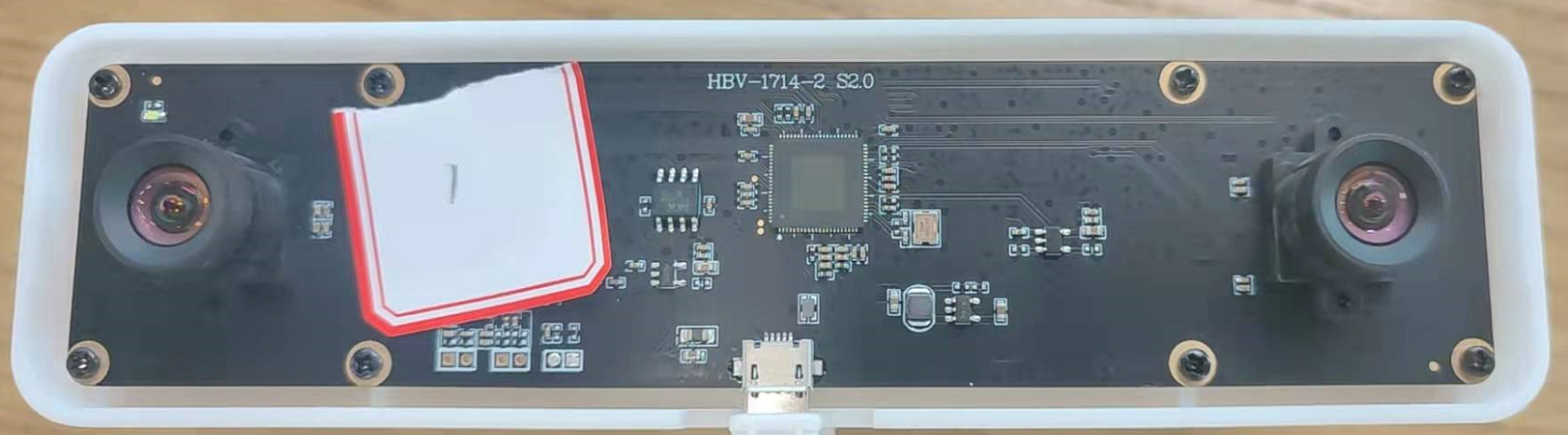
Camera: USB binocular camera, supporting UVC standard protocol
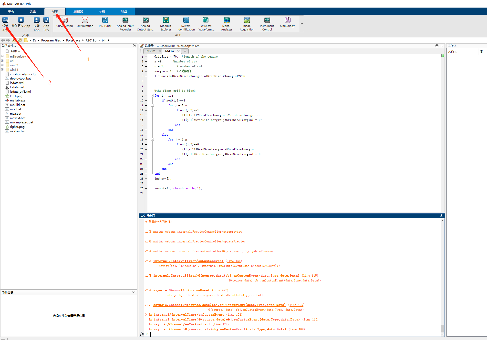
1. Install the OS Generic Video Interface
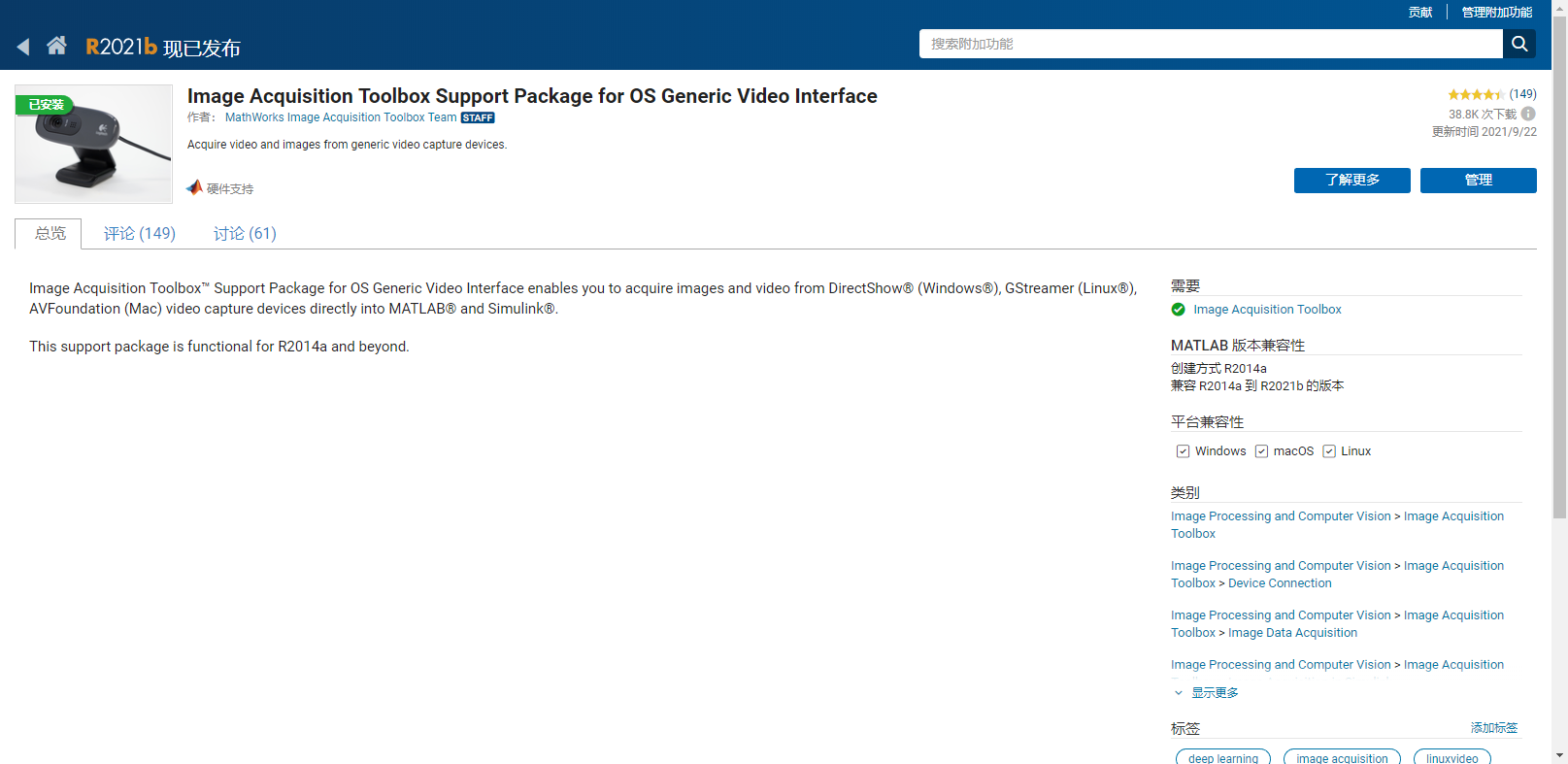
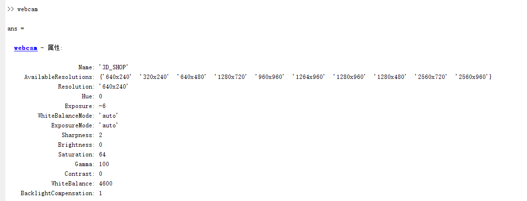
Plug in the camera and enter the command (webcam) in the Matlab command line window. If the following interface appears, the installation is successful:
2. Test camera
-
Execute clear ans, clear the results obtained by just executing webcam, and disconnect the camera. (Note: since the webcam command was executed in the previous step, Matlab automatically connected the camera by default. Here, clear ans to clear the connected camera first)
-
Execute webcam(1) or webcam('3D_SHOP '), (Note: the' 3D_SHOP 'here is obtained from the name element in ans. if there are multiple cameras, there will be multiple names. You can specify which name to connect) to connect the cameras.
-
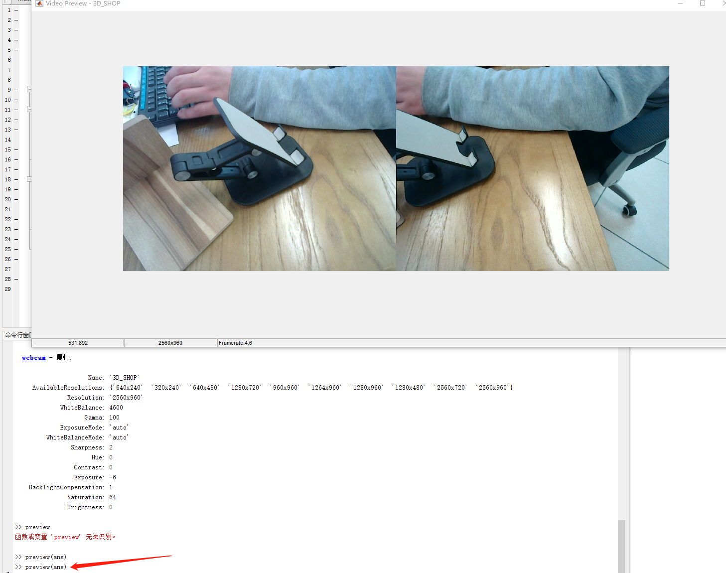
Set sub resolution

- Show video stream
2, Preparations before calibration

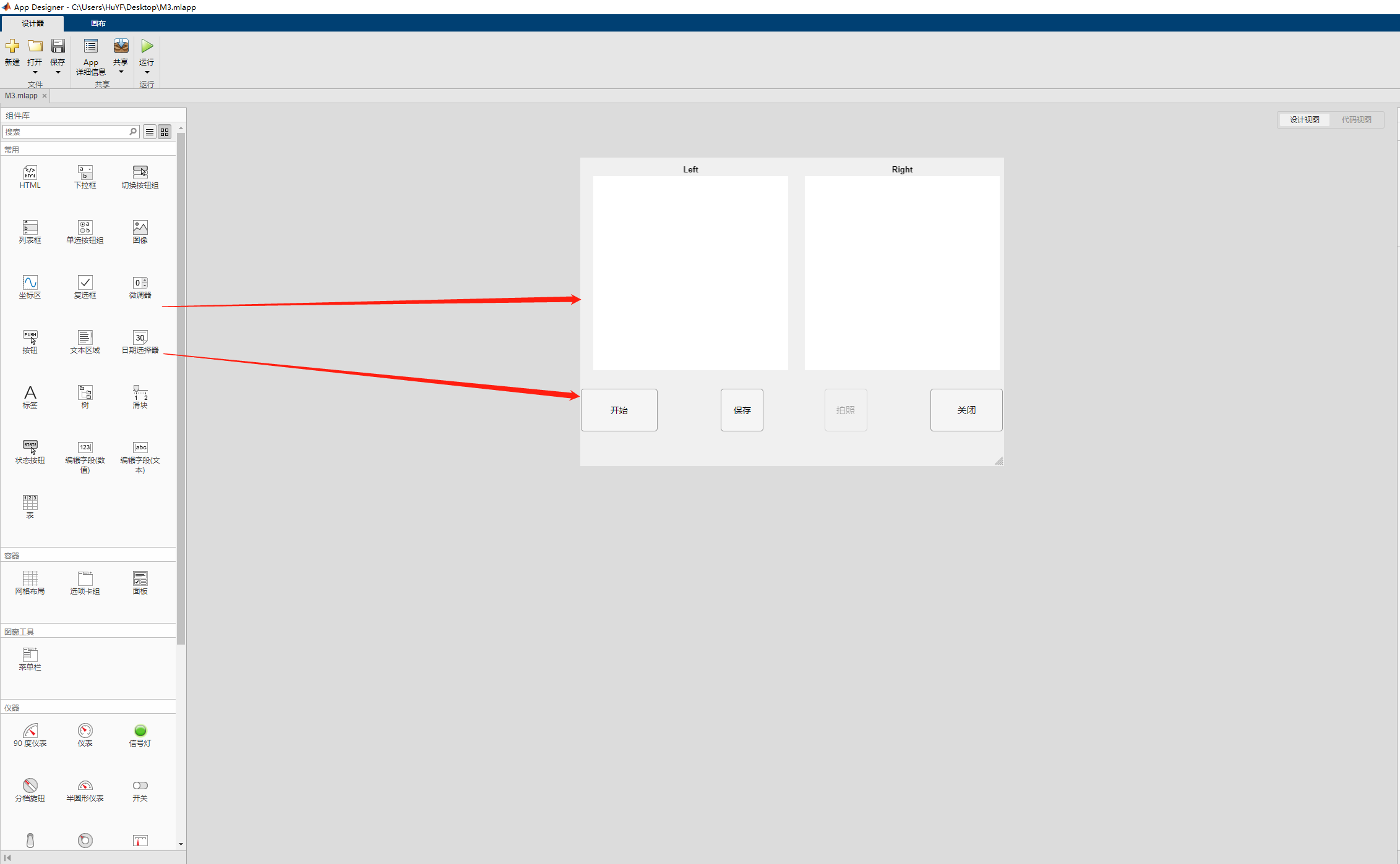
1. Design GUI
Before calibration, we need to collect image data first. In order to facilitate subsequent image acquisition, we first design a simple binocular camera photographing GUI, as shown in the figure above. Open the GUI design APP of Matlab. As shown in the figure below.

1) Design interface
2) Switch to code interface

classdef M3 < matlab.apps.AppBase

    % Properties that correspond to app components
    properties (Access = public)
        UIFigure    matlab.ui.Figure
        GridLayout  matlab.ui.container.GridLayout
        camLeft     matlab.ui.control.UIAxes
        startCam    matlab.ui.control.Button
        recordCam   matlab.ui.control.Button
        closeCam    matlab.ui.control.Button
        camRight    matlab.ui.control.UIAxes
        saveButton  matlab.ui.control.Button
    end


    properties (Access = private)
    end

    properties (Access = public)
        cam % Description
        reImage = 0
        imageLeft % Description
        imageRight % Description
        camImage % Description
        saveUrl = '0'
    end


    % Callbacks that handle component events
    methods (Access = private)

        % Button pushed function: startCam
        function startCamButtonPushed(app, event)
            app.cam=webcam(1)
            app.cam.Resolution = '2560x960'
            app.camImage = snapshot(app.cam)
            im=image(app.camLeft, zeros(size(app.camImage), 'uint8'))
            axis(app.camLeft, 'image')
            preview(app.cam, im)

        end

        % Button pushed function: closeCam
        function closeCamButtonPushed(app, event)
            delete(app)
        end

        % Button pushed function: recordCam
        function recordCamButtonPushed(app, event)
            app.camImage = snapshot(app.cam)
            im = image(app.camRight, app.camImage)
            axis(app.camRight, 'image')
            app.imageLeft = app.camImage(1:960, 1:1280, 1:3)
            app.imageRight = app.camImage(1:960, 1281:2560, 1:3)
            app.reImage = app.reImage + 1
            imwrite(app.imageLeft, sprintf('%s%s%d%s', app.saveUrl, '\left', app.reImage, '.bmp'))
            imwrite(app.imageRight, sprintf('%s%s%d%s', app.saveUrl, '\right', app.reImage, '.bmp'))
        end

        % Button pushed function: saveButton
        function saveButtonPushed(app, event)
            app.saveUrl = uigetdir('\.')
            if(app.saveUrl ~= '0')
                app.recordCam.Enable = true
            end
        end
    end

    % Component initialization
    methods (Access = private)

        % Create UIFigure and components
        function createComponents(app)

            % Create UIFigure and hide until all components are created
            app.UIFigure = uifigure('Visible', 'off');
            app.UIFigure.Color = [0.9412 0.9412 0.9412];
            app.UIFigure.Position = [100 100 685 499];
            app.UIFigure.Name = 'UI Figure';
            app.UIFigure.Scrollable = 'on';

            % Create GridLayout
            app.GridLayout = uigridlayout(app.UIFigure);
            app.GridLayout.ColumnWidth = {'1.8x', 99.99, '1x', 44, 50.99, '1x', 99.99, '1.7x'};
            app.GridLayout.RowHeight = {'5.12x', '1x', 36};
            app.GridLayout.ColumnSpacing = 1.22318522135417;
            app.GridLayout.Padding = [1.22318522135417 10 1.22318522135417 10];

            % Create camLeft
            app.camLeft = uiaxes(app.GridLayout);
            title(app.camLeft, 'Left')
            xlabel(app.camLeft, '')
            ylabel(app.camLeft, '')
            app.camLeft.XColor = [1 1 1];
            app.camLeft.XTick = [];
            app.camLeft.YColor = [1 1 1];
            app.camLeft.YTick = [];
            app.camLeft.ZColor = [1 1 1];
            app.camLeft.TitleFontWeight = 'bold';
            app.camLeft.Layout.Row = 1;
            app.camLeft.Layout.Column = [1 4];

            % Create startCam
            app.startCam = uibutton(app.GridLayout, 'push');
            app.startCam.ButtonPushedFcn = createCallbackFcn(app, @startCamButtonPushed, true);
            app.startCam.HandleVisibility = 'off';
            app.startCam.BusyAction = 'cancel';
            app.startCam.IconAlignment = 'center';
            app.startCam.FontSize = 14;
            app.startCam.Layout.Row = 2;
            app.startCam.Layout.Column = 1;
            app.startCam.Text = 'start';

            % Create recordCam
            app.recordCam = uibutton(app.GridLayout, 'push');
            app.recordCam.ButtonPushedFcn = createCallbackFcn(app, @recordCamButtonPushed, true);
            app.recordCam.HandleVisibility = 'off';
            app.recordCam.BusyAction = 'cancel';
            app.recordCam.IconAlignment = 'center';
            app.recordCam.FontSize = 15;
            app.recordCam.Enable = 'off';
            app.recordCam.Layout.Row = 2;
            app.recordCam.Layout.Column = 6;
            app.recordCam.Text = 'photograph';

            % Create closeCam
            app.closeCam = uibutton(app.GridLayout, 'push');
            app.closeCam.ButtonPushedFcn = createCallbackFcn(app, @closeCamButtonPushed, true);
            app.closeCam.HandleVisibility = 'off';
            app.closeCam.BusyAction = 'cancel';
            app.closeCam.IconAlignment = 'center';
            app.closeCam.FontSize = 15;
            app.closeCam.Layout.Row = 2;
            app.closeCam.Layout.Column = 8;
            app.closeCam.Text = 'close';

            % Create camRight
            app.camRight = uiaxes(app.GridLayout);
            title(app.camRight, 'Right')
            xlabel(app.camRight, '')
            ylabel(app.camRight, '')
            app.camRight.XColor = [1 1 1];
            app.camRight.XTick = [];
            app.camRight.YColor = [1 1 1];
            app.camRight.YTick = [];
            app.camRight.ZColor = [1 1 1];
            app.camRight.TitleFontWeight = 'bold';
            app.camRight.Layout.Row = 1;
            app.camRight.Layout.Column = [5 8];

            % Create saveButton
            app.saveButton = uibutton(app.GridLayout, 'push');
            app.saveButton.ButtonPushedFcn = createCallbackFcn(app, @saveButtonPushed, true);
            app.saveButton.IconAlignment = 'center';
            app.saveButton.FontSize = 14;
            app.saveButton.Layout.Row = 2;
            app.saveButton.Layout.Column = 3;
            app.saveButton.Text = 'preservation';

            % Show the figure after all components are created
            app.UIFigure.Visible = 'on';
        end
    end

    % App creation and deletion
    methods (Access = public)

        % Construct app
        function app = M3

            % Create UIFigure and components
            createComponents(app)

            % Register the app with App Designer
            registerApp(app, app.UIFigure)

            if nargout == 0
                clear app
            end
        end

        % Code that executes before app deletion
        function delete(app)

            % Delete UIFigure when app is deleted
            delete(app.UIFigure)
        end
    end
end

In the figure above, the white part is the code I added, and the others are generated by Matlab APP GUI.
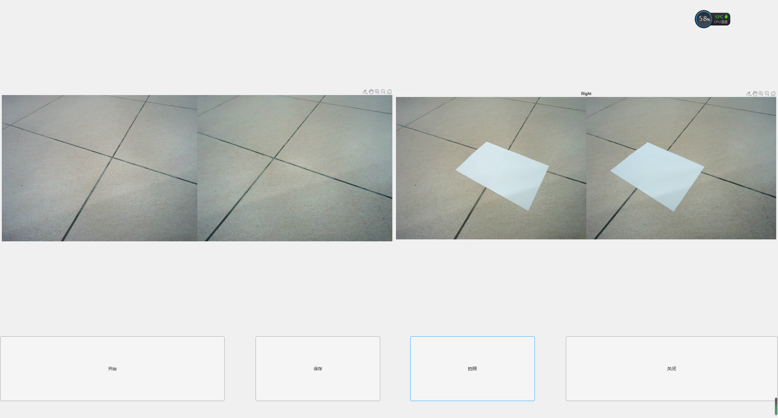
3) GUI operation method

Start: GUI connect camera
Save: select the path where the picture will be saved
Take photos: take photos and save photos
2. Design checkerboard with Matlab
close all;
clear all;
clc;
width=1024  ;      %pattern Width of
height=768     ;          %pattern High
img_final=zeros(height,width);
reinforceconner=0       ;%Strengthen corners
row=10;                 %pattern The number of rows in a checkerboard
col=13 ;              %pattern The number of columns in a checkerboard
length=45;           %pattern The size of the middle chessboard
org_X=(height-row*length)/2;        %pattern For the position in the longitudinal axis direction, it is placed in the middle by default
org_Y=(width-col*length)/2;             %pattern The position in the horizontal axis direction is placed in the middle by default
  color1=1;
     color2=color1;
img=zeros(row*length,col*length);
for i=0:(row-1)
    color2=color1;
    for j=0:(col-1)
        if color2==1
        img(i*length+1:(i+1)*length-1,j*length+1:(j+1)*length-1)=color2;
        end
        %If you don't add it, you can comment it out
        %
        color2=~color2;
    end
    color1=~color1;
end
img_final(org_X:org_X+row*length-1,org_Y:org_Y+col*length-1)=img;
   img_final=~img_final;
     figure;imshow(img_final);
     imwrite(img_final, 'cheesBoard.bmp','bmp');
Quoted from zhouye lihuahttp://blog.csdn.net/zhouyelihua/article/details/46674191

3, Collect images and calibrate the dual target machine
Stereocamera calibrator: Matlab binocular camera calibration toolbox
Add a knowledge:
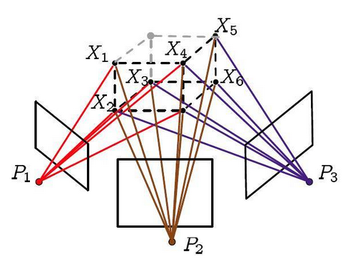
***Re projection: * * * re projection refers to the second projection of.
-
In fact, the first projection refers to the projection of three-dimensional space points onto the image when the camera takes pictures.
-
Then we use these images to analyze some feature points Triangulation (triangulation), using geometric information( Antipolar geometry )Construct triangles to determine the location of 3D space points
-
Finally, we use the coordinates of the three-dimensional points we calculated (note that they are not real) and the camera pose we calculated (of course, they are not real) for the second projection, that is, re projection.
**Epipolar geometry: epipolar geometry constraint is a point to line constraint, not a point to point constraint. Nevertheless, epipolar constraint gives important constraints for corresponding points. It compresses the matching of corresponding points from the search of the whole image to the search of corresponding points on a straight line. In stereo vision measurement, stereo matching (matching of corresponding points) is a key technology, in which epipolar geometry plays an important role. In stereo vision system, two cameras shoot an entity point in physical space at different angles, and there are two imaging points on two images respectively. Stereo matching is to know one imaging point and find the corresponding point of the imaging point - limit on the other image Searching (Lecture 13.2 by Gao Xiang). Epipolar geometric constraint is a commonly used matching constraint technology. (Mastering OpenCV with Practical Computer Vision Projects)
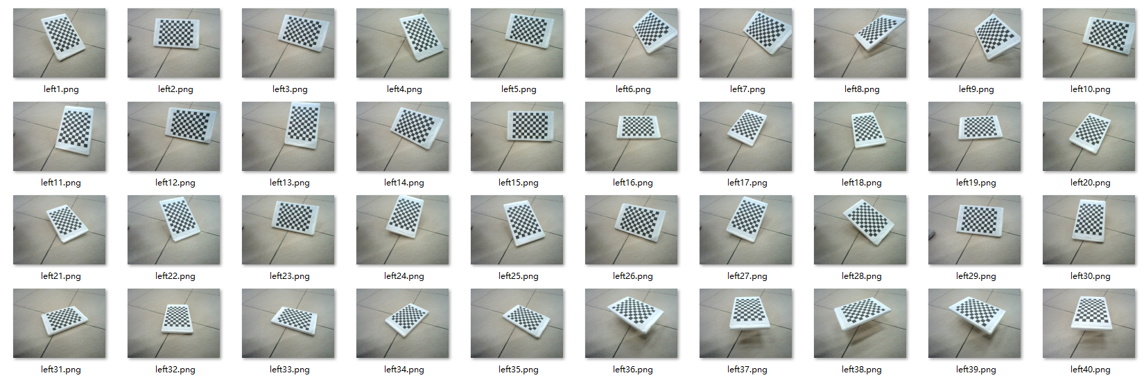
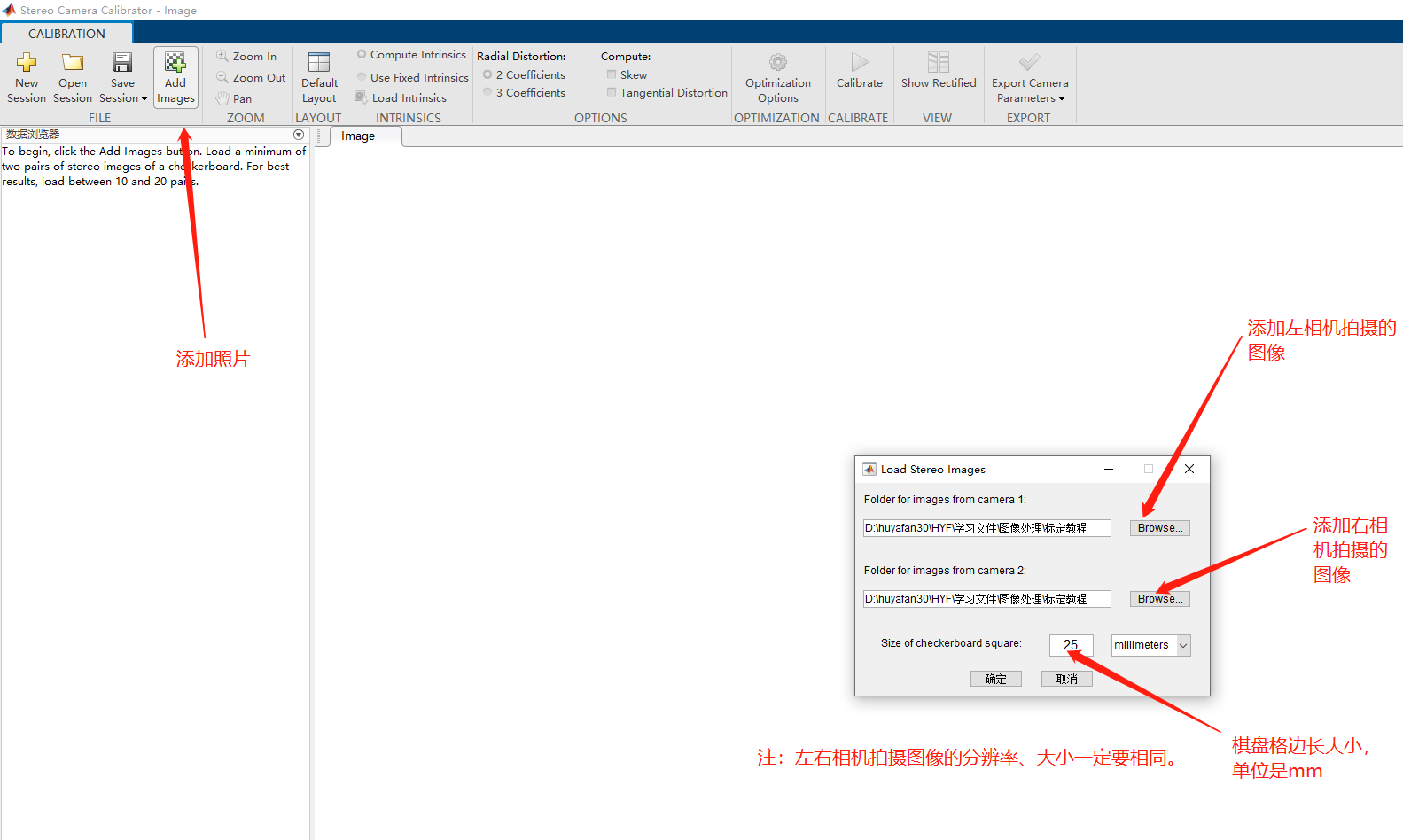
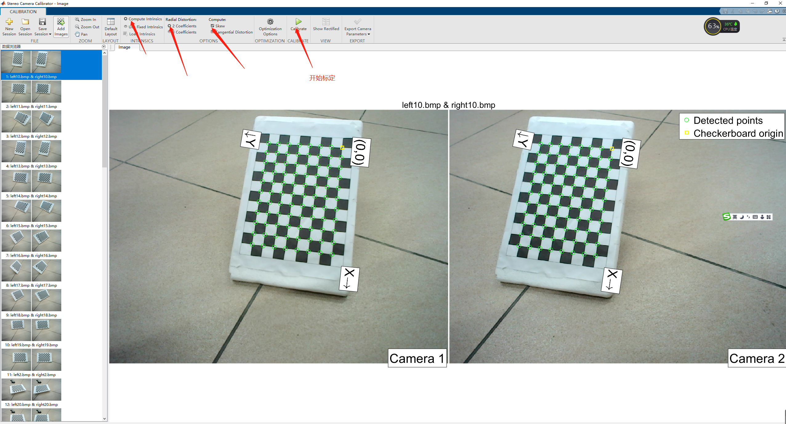
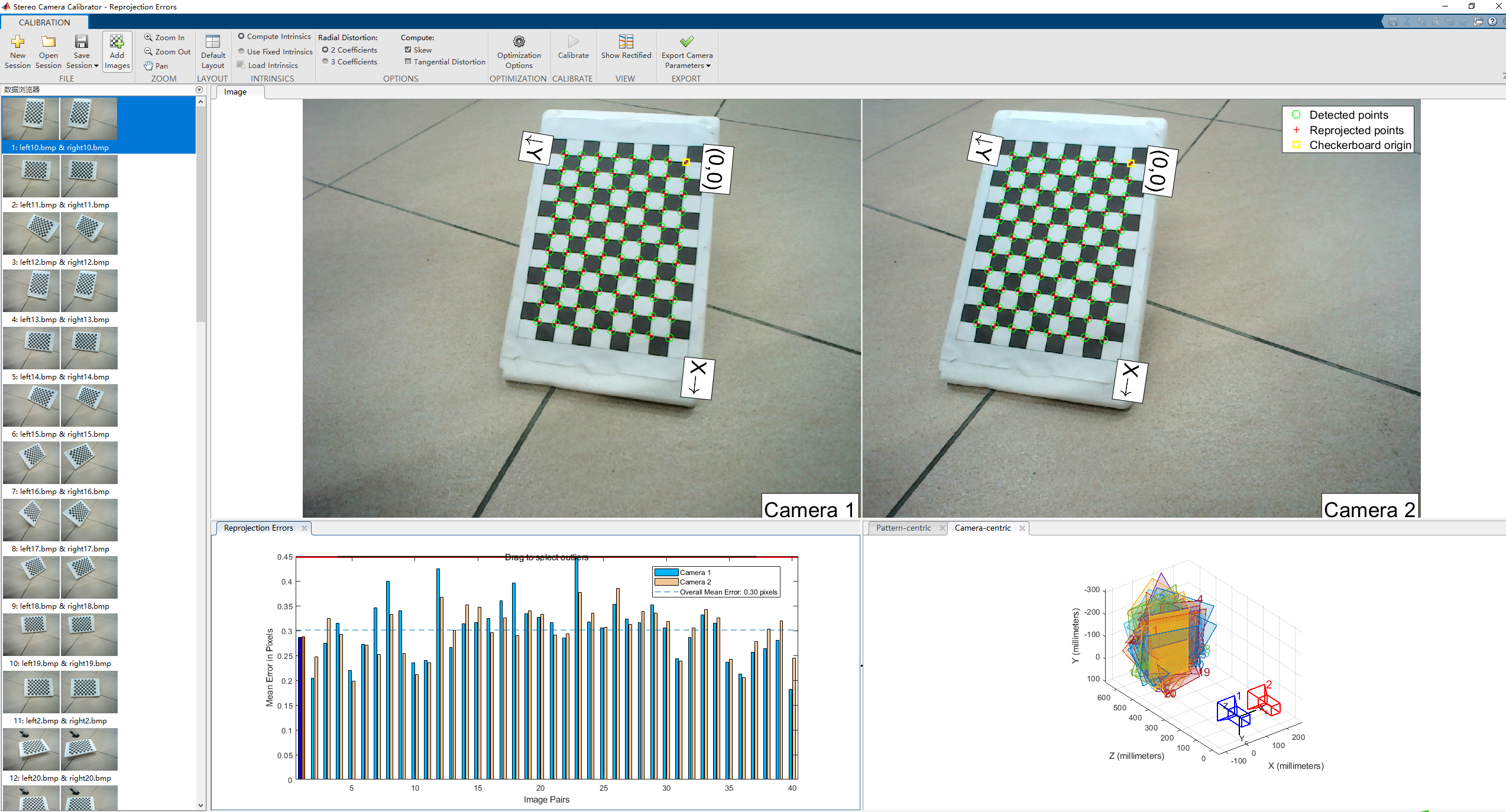
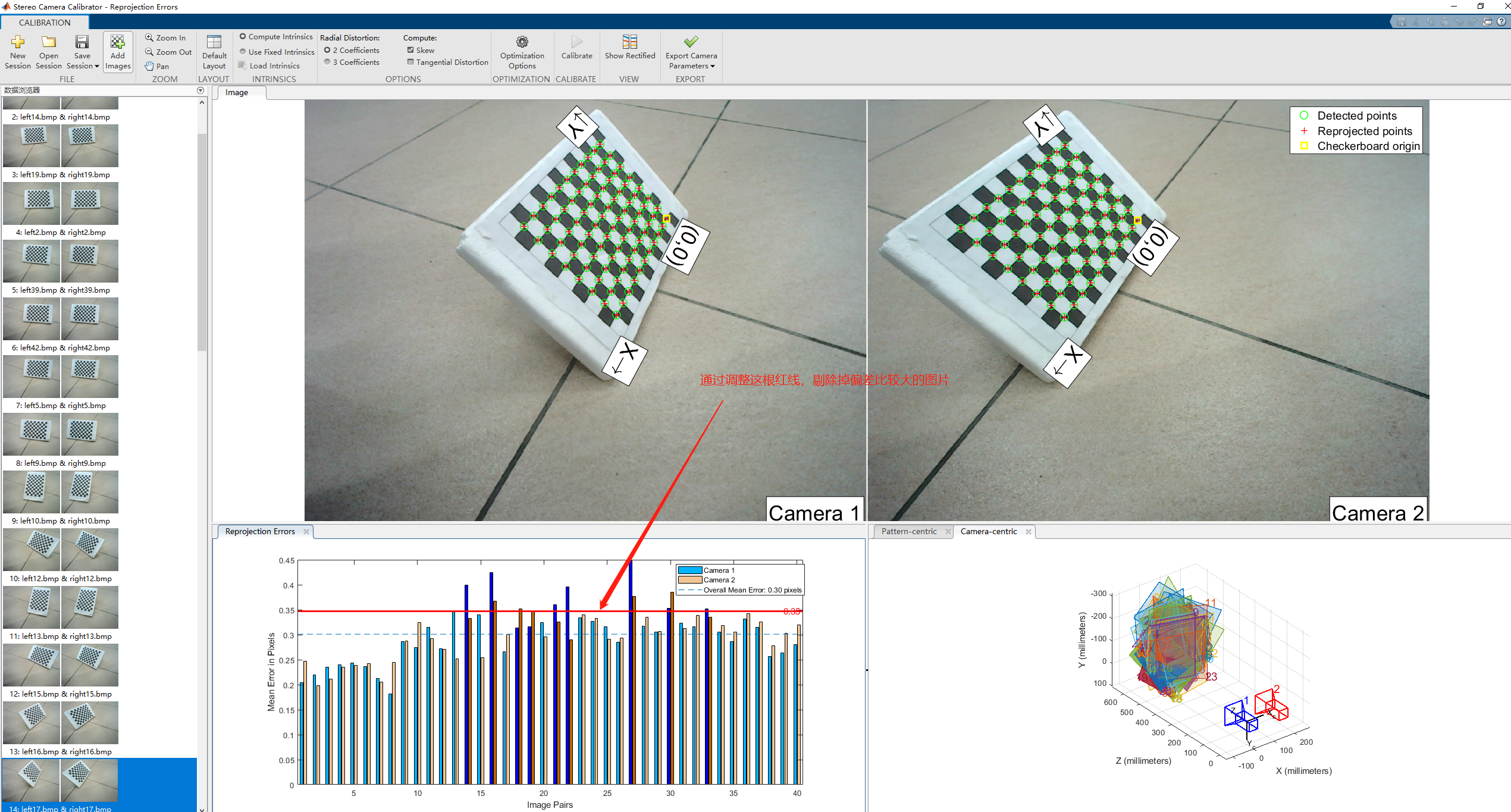
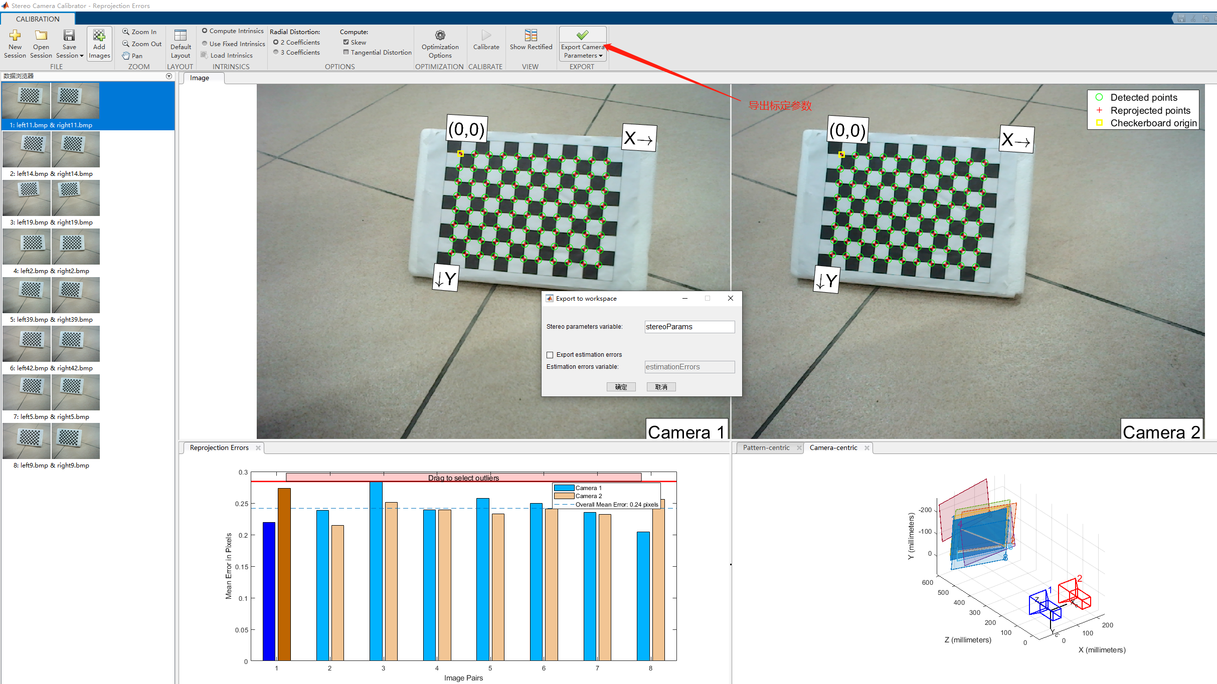
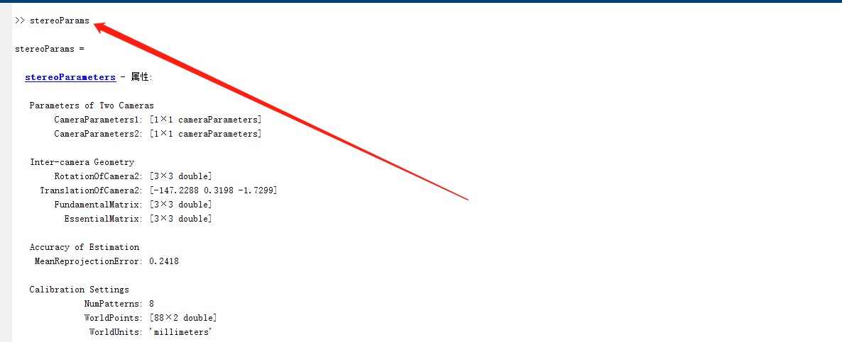
1. Binocular camera calibration using stereocamera calibrator toolbox in Matlab


2. Supplement (the following is quoted from Experience of improving calibration accuracy of monocular camera_ zilanpotou182 blog - CSDN blog_ Improve camera calibration accuracy)
In order to improve the calibration accuracy of monocular camera, I have carefully read the original text of Zhang Zhengyou's calibration method and learned some great methods on the Internet, but most of the time they are very general. I have summarized these experiences and tested them. The reliable conclusions are listed below:
(1) During calibration, the angle between the plane where the calibration template is located and the image plane cannot be too small. The experiment shows that when the angle between the two is small, there will be a great error.
(2) For the relative pose between the image fixing plate and the camera, generally, the calibration plate should occupy about half of the area of the whole image, and the calibration plate should have front view, bottom view, top view, left squint and right squint relative to the camera;
(3) The position and attitude of the calibration plate have much more influence on the calibration results than the number of calibration photos;
(4) The calibration plate must be flat, otherwise the error is great, and the flatness of the calibration plate is the most important factor;
(5) The sequence of photos used for shooting has little effect on the results. The first five digits after the decimal point are the same, and the random selection of one result has little effect;
(6) According to the original text of Zhang Zhengyou's calibration method, the photographing sequence is to start from facing the image, select a coordinate axis each time, rotate an angle of 45 degrees, and shoot about 16 pictures, but it feels that the angle can be a little smaller;
-----------------------------------Split line------------------------------
List the shooting angle schemes in your own experiment at that time. The results of shooting calibration of these seven schemes have no problem in distorting, but the displacement of the optical center is a little different. They all offset to the lower right, but the offset is different. Later, the scheme with the best effect should be scheme 6, but the advantage is not obvious. If someone wants to do this experiment in the future, you can look at my unsuccessful cases first, which may save time.
Scheme 1: there are three groups, 14 in front view, 14 in bottom view and 14 in top view. All photos rotate only relative to the horizontal axis. The front view photos account for three-quarters of the camera's field of view and the elevation photos account for one-quarter of the camera's field of view. The 14 photos in each group draw a rectangular outline, 2 in the middle and 12 around;
Scheme 2: three groups, 14 in front, 14 in bottom and 14 in top, The front view photos have no corner (no rotation), and the bottom view and top view photos face the camera in a fan shape (both around the horizontal axis and the vertical axis). The front view photos account for three quarters of the camera's field of vision, and the top view photos account for one quarter of the camera's field of vision. 14 photos draw a rectangular outline, 2 in the middle and 12 around;
Scheme 3: others are the same as scheme 2, except that the photos looking up and down are wedged towards the camera;
Scheme 4: there are three groups, 14 in front view, 14 in bottom view and 14 in top view. All the photos in front view, bottom view and top view face the camera in a fan shape. The front view photos account for three quarters of the camera's field of vision, and the elevation photos account for one quarter of the camera's field of vision. The 14 photos draw a rectangular outline, 2 in the middle and 12 around;
Scheme 5: the others are the same as scheme 4, except that the photos are wedge-shaped facing the camera;
Scheme 6: first take four front views, then four left far right near (that is, the left side of the calibration board is far from the camera, the right side is close to the camera, the same below), four left near right far, four upper far lower near, four upper near lower far - neither wedge nor fan.
Scheme 7: on the middle line of the long axis, change the angle evenly, take 9 pictures, on the middle line of the short axis, change the angle evenly, take 9 pictures, and then make up one picture at each of the four corners. 22 sheets in total.