catalogue
1. Experiment contents and steps:
2. Set the read / write cycle (i.e. 4)
5. Set AHB, APB1 and APB2 (i.e. 6)
5. Program design (Standard Library)
6. Program design (HAL Library)
4. System clock configuration
1. Experiment contents and steps:
Experiment content:
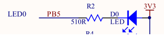
Comment out the clock in the library and write the clock configuration manually. Judge whether the clock is on by the flashing speed of the LED. When there is no clock, the built-in 8MHz clock is used, so the LED flashes slowly. The configured system clock bit is 72MHz, so the LED flashes faster.
Steps:
Configure according to RCC clock tree.
2. Hardware description
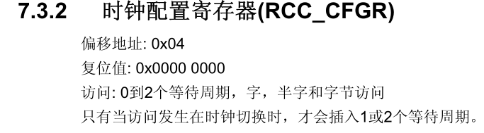
3. Register description
Clock tree: (STM32 Chinese reference manual P56)

1. Set PLL (i.e. 1,2,3)
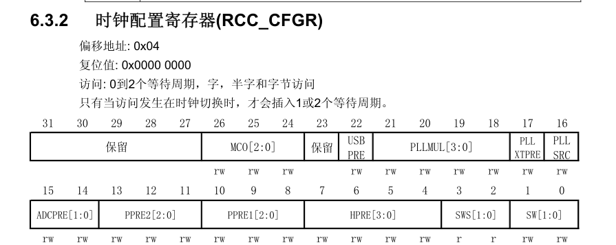
Set PLLXTPRE:
When it is configured as 0, i.e. no frequency division, it should be configured as 0 in this experiment. RCC_ CFGR &= 0xFFFD FFFF;
Set PLLSRC:
Select HSE as PLL clock input. The experimental configuration is 1. RCC_CFGR |= 0x0001 0000;
PLLMUL:
Because the maximum clock of STM32F1 is 72MHz and PLLMUL is the frequency doubling factor, the maximum is 9. At this time, the system clock is 72MHz.
RCC_ CFGR &= 0xFFC3 FFFF; (clear PLLMUL)
RCC_CFGR |= 0x001C 0000; (set to 9 octave)
2. Set the read / write cycle (i.e. 4)
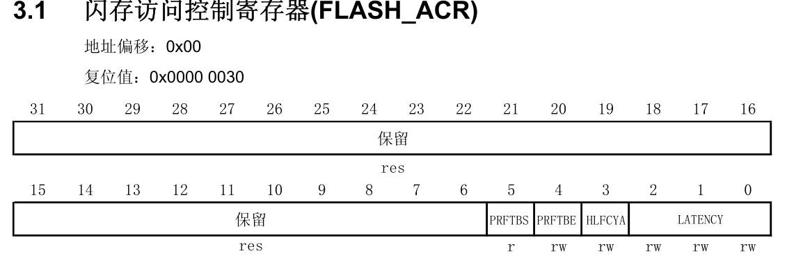
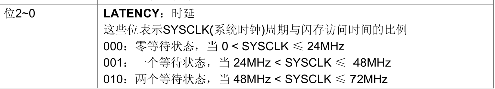
By configuring flash_ Set the delay of system cycle reading by [2-0] of ACR register. In this experiment, set the system clock to 72MHz, so set it to two waiting states (010).
FLASH_ ACR &= 0xFFF8; (please [2-0])
FLASH_ACR |= 0x0002; (set two waiting States)
3. Start HSE and PLL

Start HSE configuration RCC_CR[16] bit, set to 1 on, and then pass RCC_CR[17] judge whether the HSE clock is on; Turn on PLL to configure RCC_CR[24] bit, set to 1 on, after passing RCC_ The CR [25] bit determines whether the PLL is successfully opened.
RCC_CR |= 0x0101 0000; / / (start HSE, PLL)
While((RCC_CR &0x0202 0000) != 0x0202 (0000) / / wait for HSE and PLL to start
4. Set SW (i.e. 5)
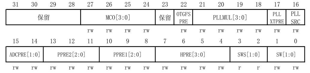
Set RCC_CFGR[1-0] selects PLL as the system clock and is configured as 10. Available through RCC_CFGR[3-2] to determine whether the setting is successful.
RCC_ CFGR &= 0xFFFF FFFC; / / clear SW
RCC_CFGR |= 0x0000 0002; / / select PLL as the system clock
While((RCC_CFGR&0x0000 0008) != 0x0000 (0008) / / wait
5. Set AHB, APB1 and APB2 (i.e. 6)
Set AHB=APB2=72MHz, APB1=36MHz (the maximum should be 72MHz)
RCC_CFGR[7-4] -> AHB
RCC_CFGR[10-8] -> APB1
RCC_CFGR[13-11] -> APB2
RCC_ CFGR &= 0xFFFF C00F; / / empty
RCC_CFGR |= 0x0000 0400; / / no frequency division for AHB, APB2 and APB1 2
4. Program design (register)
Source code: here is the key part selected by Shuai. See the source code in detail.
void SystemInit(void)
{
    //PLLXTPRE
    RCC->CFGR &= 0xFFFDFFFF;
    //PLLSRC
    RCC->CFGR |= 0x00010000;
    //Set PLLMUL
	RCC->CFGR &= 0xFFC3FFFF;	    //Empty PLLMUL
	RCC->CFGR |= 0x003C0000;		//Set to 9 octave

    //Set read / write cycle
	FLASH->ACR &= 0xFFF8;	//Please [2-0]
	FLASH->ACR |= 0x0002;	//Set two waiting States

    //Start HSE and PLL
    RCC->CR |= 0x01010000;	//Start HSE, PLL
	while((RCC->CR &0x02020000) != 0x02020000){};	//Wait for HSE, PLL on

    //Set SW
    RCC->CFGR &= 0xFFFFFFFC;		//Empty SW
	RCC->CFGR |= 0x00000002;		//Select PLL as the system clock
	while((RCC->CFGR&0x00000008) != 0x00000008){};	//wait for

    //Set AHB, APB1, APB2
	RCC->CFGR &= 0xFFFFC00F;	    //empty
	RCC->CFGR |= 0x00000400;		//AHB, APB2 do not divide, APB1 2 divide
}
5. Program design (Standard Library)
1. Set two waiting cycles (in stm32f10x_flash.c)
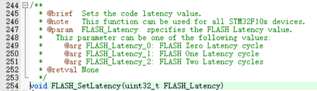
Set the waiting period to 2 cycles,
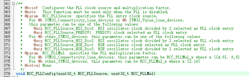
2. Configure PLL (in stm32f10x_rcc.c)
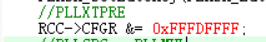
PLLXTPRE configuration: configured as 0 without frequency division. (the configured function is not found in the standard library, so it is configured with registers)
Pllsrc, pllmul configuration: the first parameter is RCC_PLLSource_HSE_Div1, no frequency division; The second parameter is RCC_PLLMul_9, i.e. 9 times the frequency, set PLLCLK=72MHz.
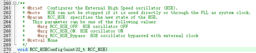
3. HSE and PLL enable (in stm32f10x_rcc.c)
HSE ENABLE: write ENABLE.
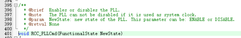
PLL ENABLE: write ENABLE.
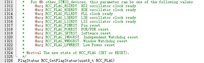
HSE and PLL enable judgment: write to RCC respectively_ FLAG_ HSERDY,RCC_FLAG_PLLRDY judges whether HSE and PLL are enabled, and returns SET if successful.

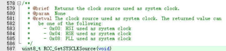
4. Set SW (i.e. system clock) (in stm32f10x_rcc.c)
Set SW: the system clock uses pllclk, so it is written to RCC_SYSCLKSource_PLLCLK.

Wait for the completion of SW setting: judge whether to set the system clock to PLLCLK through the following function. If yes, 0x80 will be returned; otherwise, other functions will be returned.

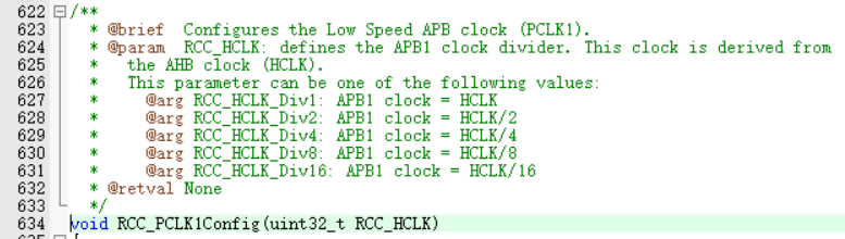
5. Set AHB, APB1 and APB2 (in stm32f10x_rcc.c)
AHB and APB2 settings: AHB=ABP2=SYSCLK=PLLCLK=72MHz. Therefore, the frequency division coefficients of AHB and ABP2 are set to 1 respectively, that is, there is no frequency division. Use the following function settings respectively.


APB1 setting: because the maximum clock of APB1 is 36MHz, it needs to be set to 2 frequency division, 72/2=36MHz. Through the following function settings.
Source code: here is the key part selected by Shuai. See the source code in detail.
void SystemInit(void)
{
//Set read / write cycle
FLASH_SetLatency(FLASH_Latency_2);//Set two waiting States
//PLLXTPRE
RCC->CFGR &= ~RCC_CFGR_PLLXTPRE;
//PLLSRC , PLLMUL
RCC_PLLConfig(RCC_PLLSource_HSE_Div1,RCC_PLLMul_9);
//Start HSE and PLL
RCC_PLLCmd(ENABLE);
RCC_HSEConfig(RCC_HSE_ON);
while(RCC_GetFlagStatus(RCC_FLAG_HSERDY)!=SET){}; //Waiting for HSERDY
while(RCC_GetFlagStatus(RCC_FLAG_PLLRDY)!=SET){}; //Wait for PLLRDY
//Set SW
RCC_SYSCLKConfig(RCC_SYSCLKSource_PLLCLK);
while(RCC_GetSYSCLKSource()!= 0x08){}; //Waiting for HSERDY
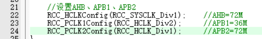
//Set AHB, APB1, APB2
RCC_HCLKConfig(RCC_SYSCLK_Div1); //AHB=72M
RCC_PCLK1Config(RCC_HCLK_Div2); //APB1=36M
RCC_PCLK2Config(RCC_HCLK_Div1); //APB2=72M
}
6. Program design (HAL Library)
To set the system clock in HAL, you only need to call two initialization functions.
1. HSE and PLL settings (in stm32f1xx_hal_rcc.c)
Structure:
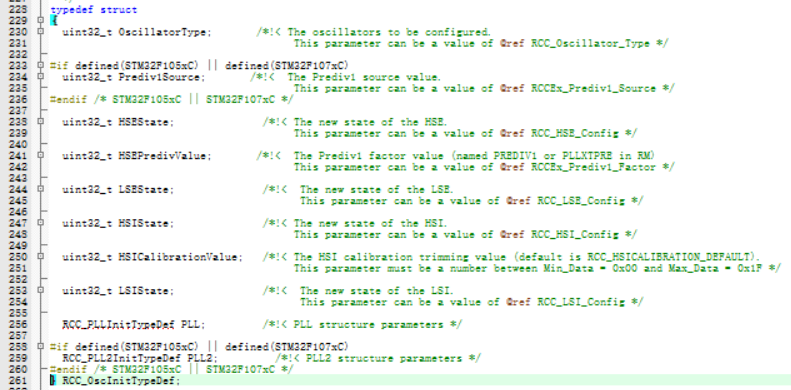
OscillatorType: set the object, HSE, HIS, LSE, LSI (here HSE)
HSEState: HSE status, whether it is on (on)
HSEPredivValue: whether HSE frequency is divided (not divided)
PLL:PLL related settings
PLL structure:
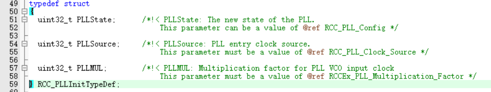
PLLState: whether PLL is enabled (enabled)
PLLSource: PLL clock source, HIS, HSE, HIS/2(HSE)
PLLMUL:PLL frequency doubling coefficient (9 times frequency)
Initialization function:

By initializing the return status of the function, wait for the setting to complete.

2. System clock configuration (in stm32f1xx_hal_rcc.c)
Structure:

ClockType: set the types SYSCLK, HCLK, PCLK1 and PCLK2 (all are set here)
SYSCLKSource: selection of system clock source HIS, HSE and PLL (here PLL)
AHBCLKDivider: AHB frequency division coefficient (no frequency division)
APB1CLKDivider: APB1 frequency division coefficient (2 frequency division)
APB2CLKDivider: APB2 frequency division coefficient (no frequency division)
Initialization function:
The first parameter is the upper structure, and the second parameter is the waiting cycle of Flash (it needs to be set to two cycles)

By initializing the return status of the function, wait for the setting to complete.

Source code: here is the key part selected by Shuai. See the source code in detail.
void SystemClock_Config(void)
{
    RCC_OscInitTypeDef RCC_OscInitStruct={0};
    RCC_ClkInitTypeDef RCC_ClkInitStruct={0};

    RCC_OscInitStruct.OscillatorType    =   RCC_OSCILLATORTYPE_HSE;     //Configure HSE
    RCC_OscInitStruct.HSEState          =   RCC_HSE_ON;                 //HSE clock on
    RCC_OscInitStruct.HSEPredivValue    =   RCC_HSE_PREDIV_DIV1;        //HSE non frequency division
    RCC_OscInitStruct.PLL.PLLState      =    RCC_PLL_ON;                //PLL enable
    RCC_OscInitStruct.PLL.PLLSource =       RCC_PLLSOURCE_HSE;          //PLL clock source HSE
    RCC_OscInitStruct.PLL.PLLMUL    =   RCC_PLL_MUL9;                   //PLL 9 frequency doubling


    while(HAL_RCC_OscConfig(&RCC_OscInitStruct)!=HAL_OK);       //Wait for PLL, HSE completion

    RCC_ClkInitStruct.ClockType  =  RCC_CLOCKTYPE_SYSCLK|RCC_CLOCKTYPE_HCLK|RCC_CLOCKTYPE_PCLK1|RCC_CLOCKTYPE_PCLK2;       //Configure SYSCLK
    RCC_ClkInitStruct.SYSCLKSource  =  RCC_SYSCLKSOURCE_PLLCLK; //SYSCLK select PLLCLK
    RCC_ClkInitStruct.AHBCLKDivider     =   RCC_SYSCLK_DIV1;
    RCC_ClkInitStruct.APB1CLKDivider    =   RCC_HCLK_DIV2;
    RCC_ClkInitStruct.APB2CLKDivider    =   RCC_HCLK_DIV1;

    while(HAL_RCC_ClockConfig(&RCC_ClkInitStruct, FLASH_LATENCY_2)!=HAL_OK){};
}
7. Experimental results
After commenting out the original system clock initialization, it will be found that the software delay flashing LED flashes very slowly.
After the system clock is configured to 72MHz, the LED flashes very fast.