Author of this series of tutorials: Xiaoyu
Official account: fish flavor ROS
QQ communication group: 139707339
Teaching video address: Station B of Xiaoyu
Full document address: Yuxiang ROS official website
Copyright notice: reprint and commercial use are prohibited unless permitted.

8.3 creating a mobile robot
Hello, I'm Xiaoyu. In this class, let's create a two wheel differential mobile robot fishbot. In the last section, we have installed radar on our robot. In this class, we will continue to improve our robot model.
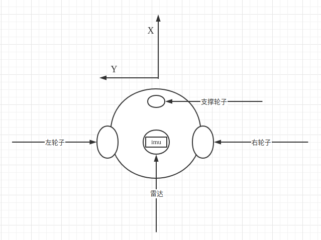
In addition to radar, robots also need IMU acceleration sensors and wheels that can be driven. In Chapter 7, we introduced robotics and two differential models, so we also need to create two differential driving wheels and one support wheel.
So in this section, Xiaoyu takes you to add the following components and joints to the robot:
- IMU sensor components and joints
- Left wheel parts and joints
- Right wheel part and joint
- Supporting wheel components and joints
1. Add IMU sensor (operation in the previous section)
IMU sensor and transparency and color modification are the homework of last class. Xiaoyu will take you to finish it first
Exercise 1: try changing the robot's body color to blue with 50% transparency (0.1 0.1 1.0 0.5)
Exercise 2: try adding imu to URDF_ Link and use imu_ The joint is fixed 2cm above the center of the car body. The geometry of imu is box, and the length, width and height are 2cm respectively
1.1 modify color
Transparency modification only needs to be done in the base_ Add material to link
<link name="base_link">
    <visual>
    	<origin xyz="0 0 0.0" rpy="0 0 0"/>
    <geometry>
    	<cylinder length="0.12" radius="0.10"/>
    </geometry>
    <material name="blue">
    	<color rgba="0.1 0.1 1.0 0.5" />
    </material>
    </visual>
</link>
1.2 add imu
  <link name="imu_link">
  	<visual>
      <origin xyz="0 0 0.0" rpy="0 0 0"/>
      <geometry>
		    <box size="0.02 0.02 0.02"/>
      </geometry>
    </visual>
  </link>

  <!-- imu joint -->
  <joint name="imu_joint" type="fixed">
      <parent link="base_link" />
      <child link="imu_link" />
      <origin xyz="0 0 0.02" />
  </joint>
2. Add right wheel
2.1 adding joints
The joint name is right_wheel_link, the wheels used by Xiaoyu when making ros2 trolley are as follows:
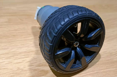
The wheel is 4cm wide and 6.4cm in diameter. The geometry is a cylinder, so the geometry configuration is as follows:
<geometry>
	<cylinder length="0.04" radius="0.032"/>
</geometry>
It should be noted that the default orientation of the cylinder is upward
We can change the rotation angle of the wheel through the rpy of origin to rotate pi/2 around the x axis, so the configuration of origin is
<origin xyz="0 0 0" rpy="1.57079 0 0"/>
The following configuration can be obtained by changing the color to black:
  <link name="right_wheel_link">
      <visual>
        <origin xyz="0 0 0" rpy="1.57079 0 0"/>
        <geometry>
          <cylinder length="0.04" radius="0.032"/>
        </geometry>
          <material name="black">
            <color rgba="0.0 0.0 0.0 0.5" />
          </material>
      </visual>
  </link>
2.2 adding a joint
We fixed the center of the left wheel at the left rear of the robot
Note the settings of origin and axis values
Look at origin first
Because base_ The height of link is 0.12, we
-
z represents the relationship between the child and the z axis of the parent. You want to fix the wheel on the lower surface of the robot, so the z downward offset of origin is 0.12 / 2 = 0.06m (the downward symbol is negative)
-
Y represents the relationship between child and parent on the y-axis, base_ The radius of link is 0.10, so we offset the negative direction of the Y axis of the wheel by 0.10m (the sign to the left is negative)
-
X represents the relationship between the child and the x-axis of the parent. The backward offset is the backward offset of the x-axis. We use a similar value of 0.02M (the backward symbol is negative)
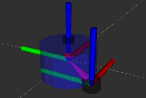
Look at axis again
The wheel will rotate. Which axis should it rotate on? It can be seen from the above figure that it is counterclockwise around the y-axis, so the setting of axis is:
<axis xyz="0 1 0" />
  <joint name="right_wheel_joint" type="continuous">
      <parent link="base_link" />
      <child link="right_wheel_link" />
      <origin xyz="-0.02 -0.10 -0.06" />
      <axis xyz="0 1 0" />
  </joint>
3. Add left wheel
The left wheel is the mapping of the right wheel, which will not be repeated
  <link name="left_wheel_link">
      <visual>
        <origin xyz="0 0 0" rpy="1.57079 0 0"/>
        <geometry>
          <cylinder length="0.04" radius="0.032"/>
        </geometry>
          <material name="black">
            <color rgba="0.0 0.0 0.0 0.5" />
          </material>
      </visual>
  </link>

  <joint name="left_wheel_joint" type="continuous">
      <parent link="base_link" />
      <child link="left_wheel_link" />
      <origin xyz="-0.02 0.10 -0.06" />
      <axis xyz="0 1 0" />
  </joint>
4. Add support wheel
The supporting wheel is fixed in front of the robot. Use a sphere with a radius of 0.016m. The diameter of the small sphere is 0.032m, which is the same as the radius of the left and right wheels. Then, the downward offset is 0.016+0.06=0.076m, and the downward value is negative. At the same time, move the supporting theory forward and choose 0.06m
The final results are as follows:
<link name="caster_link">
    <visual>
      <origin xyz="0 0 0" rpy="0 0 0"/>
      <geometry>
          <sphere radius="0.016"/>
      </geometry>
        <material name="black">
          <color rgba="0.0 0.0 0.0 0.5" />
        </material>
    </visual>
  </link>

  <joint name="caster_joint" type="fixed">
      <parent link="base_link" />
      <child link="caster_link" />
      <origin xyz="0.06 0.0 -0.076" />
  </joint>
Final URDF file: https://raw.githubusercontent.com/fishros/fishbot/master/src/fishbot_description/urdf/fishbot_base.urdf
5. Test run
5.1 compilation test
colcon build
source install/setup.bash
ros2 launch fishbot_description display_rviz2.launch.py
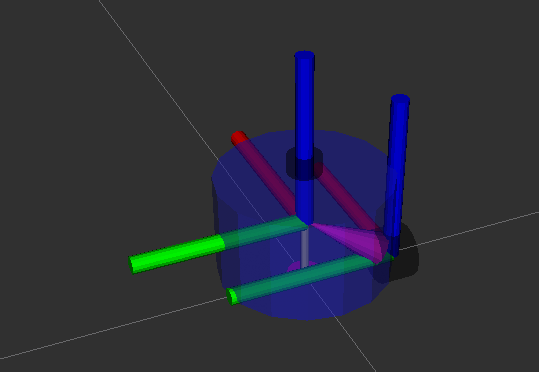
5.2 final results
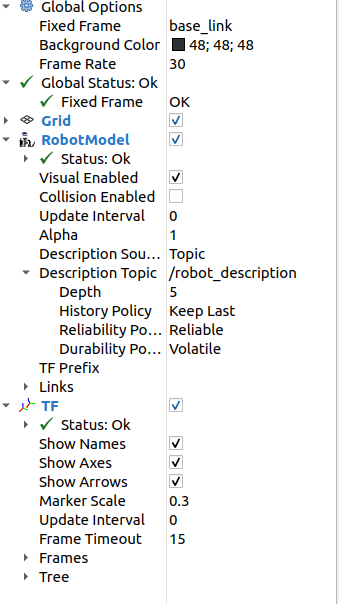
Configuration of rviz
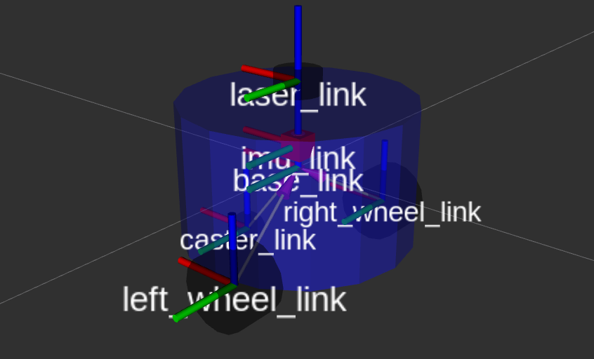
final result
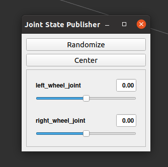
jointstate has two more sliders
Node relationship

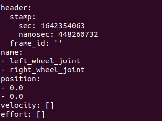
Print joint_states topic
ros2 topic echo /joint_states
5.3 through joint_state_gui changes joint angle in joint tf
In JointStatePublisher, drag the slider bar and observe
- tf transformation in rviz 2
- joint_ Transformation of values in states
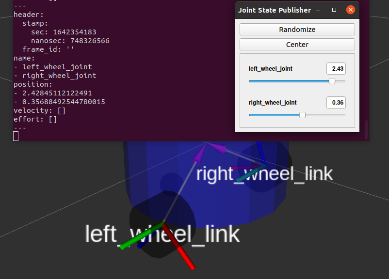
You can see that the value in the topic and the robot joint in rviz 2 are rotating synchronously as the progress bar is dragged_ States topics can also be sent manually. In the next class, Xiaoyu will take you to send a joint manually_ States to control the rotation of robot wheels
Technical exchange && questions:
-
WeChat official account and exchange group: fish flavor ROS
-
Xiaoyu wechat: AiIotRobot
-
QQ communication group: 139707339
-
Copyright protection: has joined the copyright protection program of "rights knights" (rightknights.com)
Author introduction:
I am Xiaoyu, a senior player in the field of robotics, and now I am an algorithm engineer of a biped robot in Shenzhen
Learn programming in junior high school, start to contact robots in senior high school, play robot related competitions in college, and realize a monthly income of 2W + (competition bonus)
At present, we are outputting robot learning guide, paper notes and work experience. We welcome you to pay attention to Xiaoyu, exchange technology and learn robot together