For example, I created a full screen texture vertex, but the picture does not necessarily conform to the screen scale. In this way, once the texture map is pasted, it will not conform to the picture scale as soon as it is stretched, which will be more ugly. So what temporary transformation to the vertex can maintain the scale of the rendered picture?
My basic environment settings are as follows:
glViewport(0, 0, w, h);//Setting Viewports
float ratio = (float) h / w;
frustumM(mProjMatrix, 0, -1, 1, -ratio, ratio, 1, 50);//Set projection matrix
Projection matrix setting method:
void frustumM(float *m, int offset, float left, float right, float bottom, float top, float near, float far)
{
    const float r_width = 1.0f / (right - left);
    const float r_height = 1.0f / (top - bottom);
    const float r_depth = 1.0f / (near - far);
    const float x = 2.0f * (near * r_width);
    const float y = 2.0f * (near * r_height);
    const float A = 2.0f * ((right + left) * r_width);
    const float B = (top + bottom) * r_height;
    const float C = (far + near) * r_depth;
    const float D = 2.0f * (far * near * r_depth);
    m[offset + 0] = x;
    m[offset + 5] = y;
    m[offset + 8] = A;
    m[offset + 9] = B;
    m[offset + 10] = C;
    m[offset + 14] = D;
    m[offset + 11] = -1.0f;
    m[offset + 1] = 0.0f;
    m[offset + 2] = 0.0f;
    m[offset + 3] = 0.0f;
    m[offset + 4] = 0.0f;
    m[offset + 6] = 0.0f;
    m[offset + 7] = 0.0f;
    m[offset + 12] = 0.0f;
    m[offset + 13] = 0.0f;
    m[offset + 15] = 0.0f;
}
The vertex configurations used are as follows:
createRender(-1, -ratio, 0, 2, ratio * 2, w, h);
void RenderProgramImage::createRender(float x, float y, float z, float w, float h, int windowW,int windowH) {
    //...
    mWindowW = windowW;
    mWindowH = windowH;
    initObjMatrix(); //Initialize the object matrix to the identity matrix, otherwise the following matrix operations are invalid because they are multiplied by 0
    float vertxData[] = {
            x + w, y, z,
            x, y, z,
            x + w, y + h, z,
            x, y + h, z,
    };
    memcpy(mVertxData, vertxData, sizeof(vertxData));
   //...
}
Is a typical vertex coordinate across the full screen.
The direct mapping effect is as follows:

We know that OpenGL uses a normalized coordinate system:
Therefore, we transform vertices to match the original scale of the picture through the following steps:
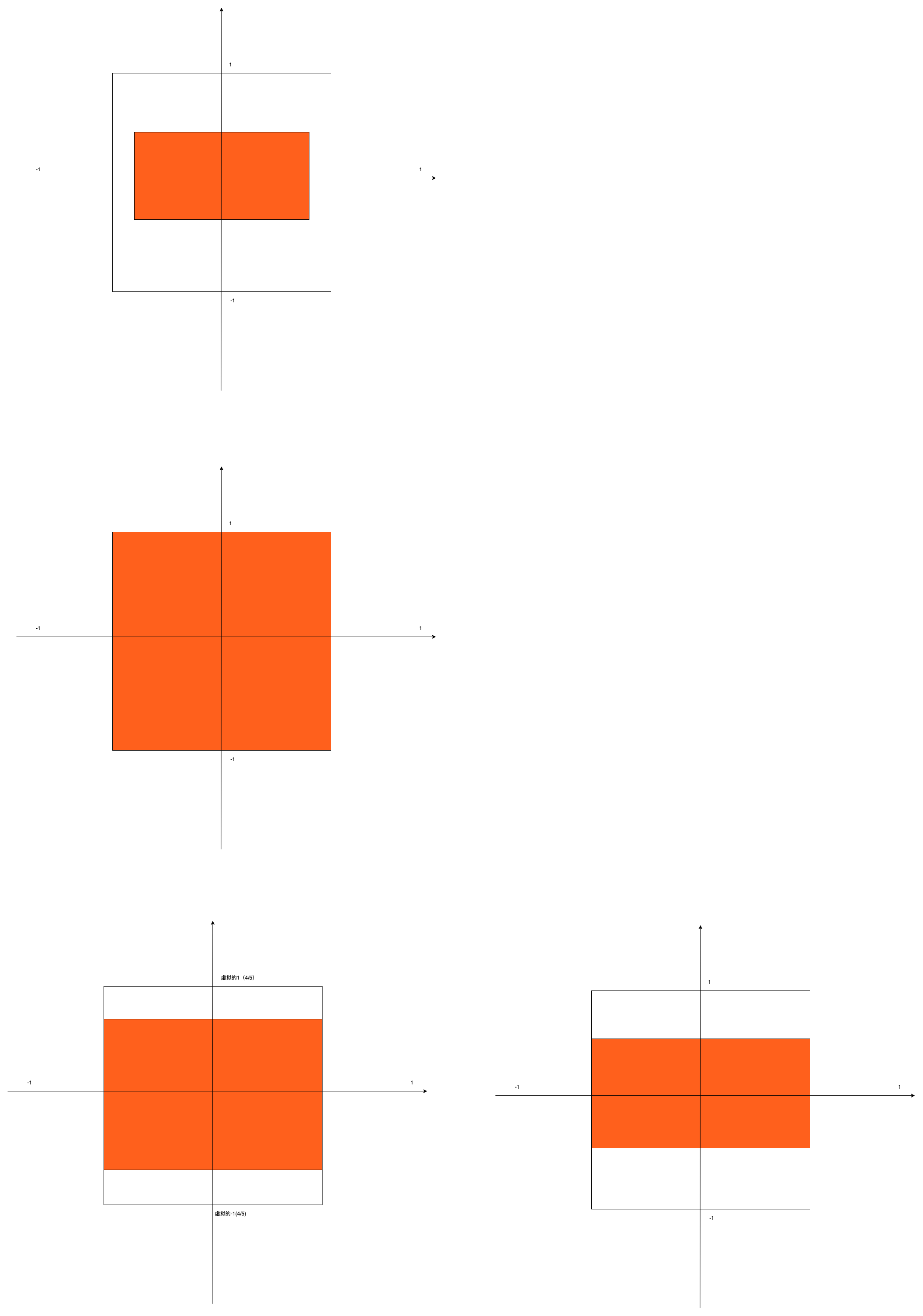
0. First, let's assume that the viewport is a square, one to one in size. Back up the current vertex transformation matrix.
1. Two ratios are obtained by dividing the width and height of the picture by the width and height of the viewport.
2. The vertex coordinates of the axis corresponding to the edge with a larger ratio do not need to be transformed. In addition, the scaling value corresponding to the edge with a smaller ratio can be multiplied by the ratio of (smaller edge / larger edge). While the longer edge fills the vertices, the vertices of the other axis can be scaled to a length consistent with the picture scale. The specific matrix operations are as follows:
3. The scale in the above step is based on the assumption that the length and width of the viewport are 1:1, but in fact, we have to multiply the scale set by the viewport to finally meet our goal when projecting to the viewport.
4. Restore the transformation matrix after drawing.
The transformation process is shown in the figure:

The implementation code is as follows:
//Keep the object and zoom the scene
    float objMatrixClone[16];
    memcpy(objMatrixClone, mObjectMatrix, sizeof(objMatrixClone));
float ratio =
                mWindowW > mWindowH ? ((float) mWindowH / (float) mWindowW) : ((float) mWindowW /
                                                                               (float) mWindowH); //Calculate the short side / long side ratio of the current viewport, so as to know the ratio of the actual length between the normalized lengths of - 1 ~ 1 of the X-axis and Y-axis
        //Determine which side of the picture can better cover the viewport length of the corresponding axis, and which side will make it full of space. The other side will be scaled according to the short side / long side ratio of OpenGL viewport. At this time, the picture with any length width ratio will become a rectangle, multiplied by the proportion of the picture itself and converted to the aspect ratio of the picture itself, so as to restore the proportion of the picture itself during texture rendering
        float widthPercentage = (float) mRenderSrcData.width / (float) mWindowW;
        float heightPercentage = (float) mRenderSrcData.height / (float) mWindowH;
        if (widthPercentage > heightPercentage) { //If the width accounts for more, stretch the width to the maximum height, readjust it to the unit of uniform density according to the viewport scale, and then adjust the scaling of the high edge of the object according to the ratio of height to width of the picture
            scale(1.0, ratio * ((float) mRenderSrcData.height / mRenderSrcData.width), 1.0); //Scale is the ratio of height to width of the picture * viewport scale
        } else {
            scale(ratio * ((float) mRenderSrcData.width / mRenderSrcData.height), 1.0, 1.0);
        }

void Layer::scale(float sx, float sy, float sz) {
    scaleM(mObjectMatrix, 0, sx, sy, sz);
}

void scaleM(float *m, int mOffset, float x, float y, float z)
{
    float sm[16];
    setIdentityM(sm, 0);
    sm[0] = x;
    sm[5] = y;
    sm[10] = z;
    sm[15] = 1;
    float tm[16];
    multiplyMM(tm, 0, m, 0, sm, 0);
    for (int i = 0; i < 16; i++)
    {
        m[i] = tm[i];
    }
}
When drawing, the vertex matrix of the object is multiplied by the camera matrix and projection matrix to determine its real position in three-dimensional space and the two-dimensional position and size projected to the plane.
void Layer::locationTrans(float cameraMatrix[], float projMatrix[], int muMVPMatrixPointer) {
    multiplyMM(mMVPMatrix, 0, cameraMatrix, 0, mObjectMatrix, 0);         //Multiply the camera matrix by the object matrix
    multiplyMM(mMVPMatrix, 0, projMatrix, 0, mMVPMatrix, 0);         //Multiply the projection matrix by the result matrix of the previous step
    glUniformMatrix4fv(muMVPMatrixPointer, 1, false, mMVPMatrix);        //Pass the final transform relationship into the render pipeline
}
Finally, it is transmitted to the uMVPMatrix of GLSL script, and then the value calculated above is multiplied by the transformation matrix:
#version 300 es\n
            uniform mat4 uMVPMatrix; //Rotate, translate, and scale the total transformation matrix. The transformation is generated by multiplying the object matrix by it
            in vec3 objectPosition; //The object position vector participates in the operation but is not output to the film source

            in vec4 objectColor; //Physical color vector
            in vec2 vTexCoord; //Intra texture coordinates
            out vec4 fragObjectColor;//Output the processed color value to the chip element program
            out vec2 fragVTexCoord;//Output the processed texture coordinates to the slice program

            void main() {
                gl_Position = uMVPMatrix * vec4(objectPosition, 1.0); //Set object position
                fragVTexCoord = vTexCoord; //By default, there is no processing, and the physical internal sampling coordinates are directly output
                fragObjectColor = objectColor; //By default, there is no processing, and the color value is output to the film source
            }
The temporary vertex transformation in line with the picture scale is realized. No matter what scale the vertex is initialized, it can be pasted according to the original scale of the picture.
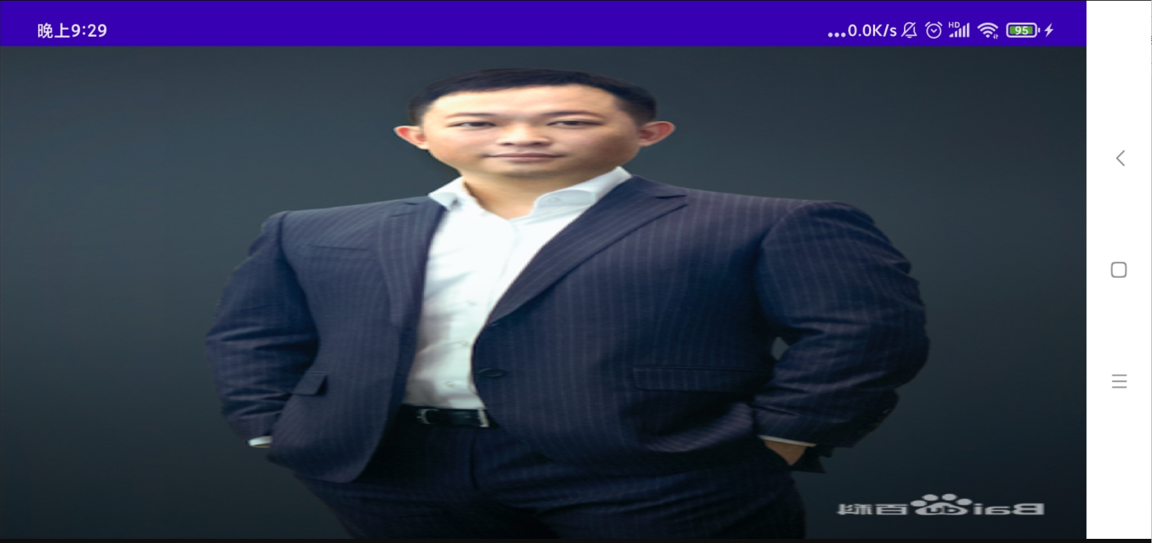
The final effect is as follows:


You can see that the photo scale is consistent regardless of the container scale.