camera_calibration
rosrun camera_calibration cameracalibrator.py --size 8x6 --square 0.108 --k 6 image:=/my_camera/image
- – size 8x6: the size of the chessboard is 8x6, and only the internal angle is calculated
- – square 0.024: the size of a square in the chessboard, in meters
- – k 6: number of radial distortion factors to use (up to 6, default 2)
- image: = subject name of the picture published by the camera
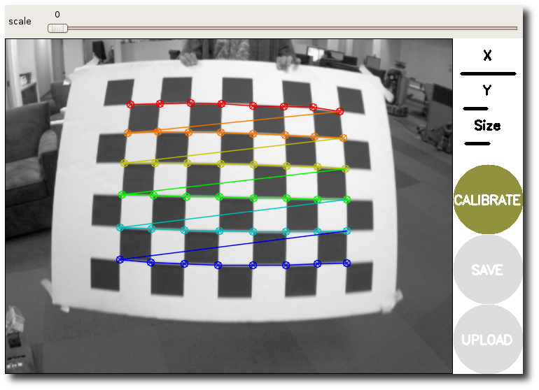
After running, subscribe to ROS original image theme and provide a calibration window. It can operate in monocular and stereo modes. The calibration window displays the current image from the camera, highlights the checkerboard, and records the calibration data. When the data is enough, press the calibration button (otherwise it is gray), and the node calculates the camera calibration parameters. When the user clicks COMMIT, the node uses the service call to upload these new calibration parameters to the camera driver.
The output camera calibration parameters are as follows:
**** Calibrating ****
mono pinhole calibration...
D = [14.565826177152536, 10.477393040343149, 1.6097304996818903e-05, -0.0038758664891502346, -21.615524616819467, 14.51314595032321, 9.0117176329534, -20.246159366771483]
K = [622.7139809471598, 0.0, 632.8545193623008, 0.0, 625.5215201440889, 369.59461579516187, 0.0, 0.0, 1.0]
R = [1.0, 0.0, 0.0, 0.0, 1.0, 0.0, 0.0, 0.0, 1.0]
P = [666.8020629882812, 0.0, 618.1466074989657, 0.0, 0.0, 662.8768310546875, 369.8623347548855, 0.0, 0.0, 0.0, 1.0, 0.0]
None
# oST version 5.0 parameters


[image]

width
1280

height
720

[narrow_stereo]

camera matrix
622.713981 0.000000 632.854519
0.000000 625.521520 369.594616
0.000000 0.000000 1.000000

distortion
14.565826 10.477393 0.000016 -0.003876 -21.615525 14.513146 9.011718 -20.246159

rectification
1.000000 0.000000 0.000000
0.000000 1.000000 0.000000
0.000000 0.000000 1.000000

projection
666.802063 0.000000 618.146607 0.000000
0.000000 662.876831 369.862335 0.000000
0.000000 0.000000 1.000000 0.000000
*Reference website link: link
parameter analysis
Distortion model
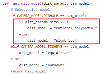
For pinhole cameras, the distortion model is divided into plumb_bob and rational_polynomial, depending on the number of radial distortion parameters K used. When K is 6, it is rational_polynomial model, others are plumb_bob.
D. K, R and P parameters
After the correction, we get the D, K, R, P parameter matrix.
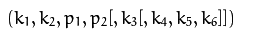
D parameter: the distortion coefficient of the camera, which belongs to the internal parameters of the camera. It can have at least 4 parameters and at most 8 parameters. Where k1, k2, k3, k4, k5, and k6 are radial distortion coefficients. p1 is the tangential p2 distortion coefficient. Specific derivation process: link
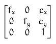
K parameter: camera matrix, CX and CY are the main points usually located in the center of the image, and FX and FY are the focal length expressed in pixels.
R parameter: usually unit matrix, which can be added if rotation is required.
P parameter: redundant information, which can be directly formed by K in ordinary monocular
Correct image with calibration parameters (image_proc)
    <!-- Generate a image_proc/rectify nodelet To correct RGB image -->
    <node pkg="nodelet" type="nodelet" name="rectify_rgb_1"
          args="load image_proc/rectify manager_1 --no-bond"
          respawn="true">
      <!-- image_mono: Uncorrected image  image_rect Corrected image  -->
      <remap from="image_mono"  to="rgb_to_depth/image_raw" />
      <param name="interpolation"  value="0" />
      <param name="queue_size"  value="2" />
      <remap from="camera_info"  to="rgb_to_depth/camera_info" />
      <remap from="image_rect"  to="rgb_to_depth/image_rect" />
    </node>
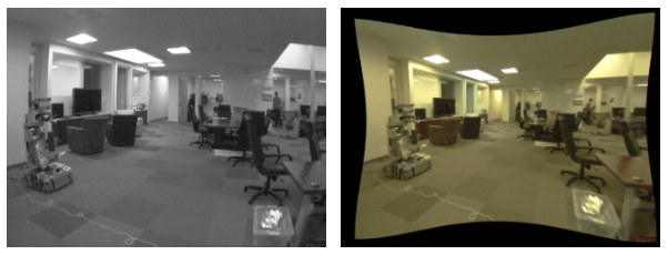
By acquiring the uncorrected image stream and its related calibration parameters, and generating the corrected image.
*Reference website link: link
Correction process

- Let's first look at the original image transformation process in the above line: first, for a point X in space, the point is projected onto the standardized undistorted image through Rt matrix and projection operation (divided by Z). In fact, each camera has lens distortion. Assuming that its distortion matrix is D, move the point to its distortion position, which is still in the normalized image. Finally, by applying the camera matrix to each image point, the normalized image is transformed into a pixel coordinate image, which is the original camera image we get.
- The correction process is to remove the influence of distortion. Firstly, the normalized undistorted image is obtained from the inverse change of the original image KD. The rotation R is the identity matrix, because we don't want to rotate the normalized undistorted image. Then K 'is converted to the pixel coordinates in the undistorted output image. Since there is no need to translate in the image plane or scale from the original image, K = K' is directly used (we can also use the optimized K obtained by monocular calibration with camera_calibration to map better).
*Reference website link: link