We are all familiar with cameras, which can map point sets in 3D space to 2D planes. This mapping process needs to be described by geometric model.
The simplest and most basic model is the pinhole camera model, which describes the basic projection and imaging inertia of the camera.
However, our commonly used cameras have lenses. Because of the lens, distortion will occur when light projection imaging. At this time, it is necessary to describe the distortion model more accurately.
In addition, it is necessary to use the camera to realize the ranging function on many occasions. Therefore, the binocular camera model and RGB-D depth camera model are also introduced here.
1, Pinhole camera model
The process of converting each point of an actual object into a pixel on an image can be summarized as
① Firstly, the coordinates of the actual point in the world coordinate system are obtained
② Convert the coordinates of the world coordinate system to the coordinates of the camera coordinate system
③ The coordinates of the camera coordinate system are mapped to a pixel on the image
1.1 imaging principle
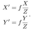
We have all done physical experiments of small hole imaging in middle school. After small hole projection, the real space point will become an inverted image on the plane. Moreover, the ratio of the distance X from the actual point to the optical axis to the distance X 'from the corresponding point to the center on the image is related to the vertical distance and focal length from the actual point to the small hole.
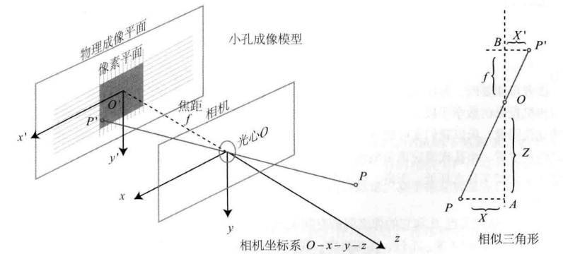
In this way, we can get the scaled image of the real object on the imaging plane. However, in the camera, we finally get pixels, so we also need to sample and quantify the image.
1.2 relationship between actual coordinates and pixel coordinates
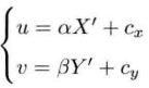
We set a pixel coordinate system ouv on the imaging plane, the origin o is in the upper left corner of the image, the u axis is parallel to the x axis in the same direction, and the v axis is parallel to the y axis in the opposite direction. In this way, there is a difference between the pixel coordinate system and the physical imaging. Let the pixel coordinates scale on the u axis α Times, scaled on the v axis β Times, the relationship is as follows:
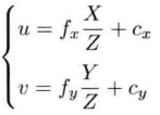
Replace X 'and Y' in the two equations with the expression of X and Y
Rewritten into matrix form, more concise and vivid
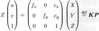
In this way, the corresponding relationship between the actual point P and the pixel point (u,v) is obtained, and the matrix composed of intermediate quantities is called the internal parameter matrix K of the camera. This internal parameter matrix is usually provided by the camera manufacturer. If not, you need to calibrate the camera yourself.
1.3 how to obtain actual coordinates
We usually say that the spatial position of a point is described based on the world coordinate system, but in the camera model, we need the position relationship of the actual point relative to the camera. Moreover, since the camera is moving, the following formula can be obtained by using the relevant knowledge of the change matrix
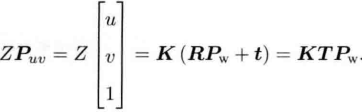
The R and t of the camera are the external parameters of the camera. The external parameters will change with the movement of the camera, but the internal parameters will not change.
2, Distorted camera model
2.1 introduction to two common distortions
In order to obtain better imaging effect, the actual camera usually adds a lens in front of the camera. The addition of the lens will affect the light propagation, that is, the real-world straight line becomes a curve in the image, which is called radial distortion. Radial distortion can be divided into barrel distortion and pillow distortion.
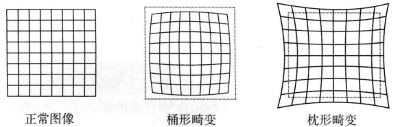
At the same time, due to the installation error, the lens and the imaging plane will not be completely parallel, and the projection position will also change. This is called tangential distortion.
2.2 de distortion method
① For radial distortion
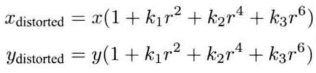
Radial distortion can be seen as the change of coordinate point along the length direction, that is, the distance between coordinate point and origin changes. The commonly used model is as follows. Assuming that the distortion becomes a polynomial relationship, three parameters K1, K2 and K3 are used to express the distortion.
Among them[
x
d
i
s
t
o
r
t
e
d
x_{distorted}
xdistorted,
y
d
i
s
t
o
r
t
e
d
y_{distorted}
ydistorted] is the normalized coordinate of the distorted point. r represents the distance between point p and the origin of the coordinate system.
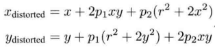
② For tangential distortion
Tangential distortion can be seen as the change of coordinate points along the tangent direction, that is, the horizontal included angle changes. Generally, P1 and P2 are used to express the tangential distortion. The specific formula is as follows.
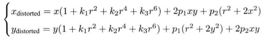
③ Comprehensive method
Combining the above two radial distortion and tangential distortion formulas, we can get a comprehensive de distortion formula, that is, we can determine the correct position of the point in the pixel plane through five distortion coefficients.
2.3 example program
#include <opencv2/opencv.hpp>
#include <string>
using namespace std;
using namespace cv;
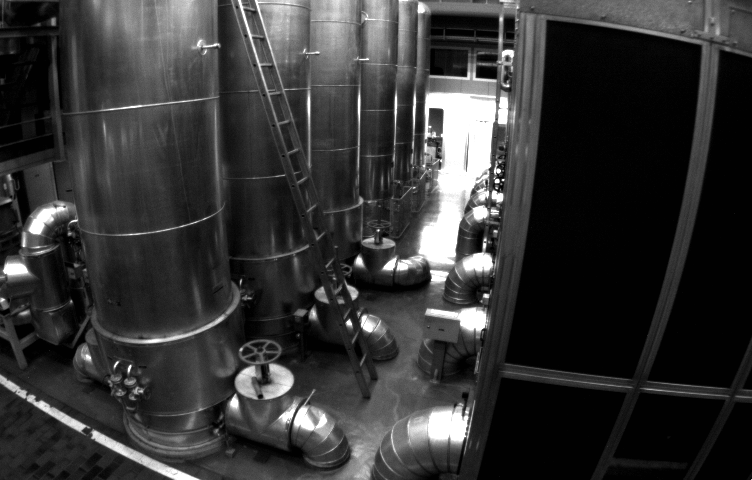
string image_file = "./distorted.png";
int main(int argc, char **argv){
//Define distortion factor
double k1 = -0.28340811, k2 = 0.07395907, p1 = 0.00019359, p2 = 1.76187114e-05;
//Camera internal parameters
double fx = 458.654, fy = 457.296, cx = 367.215, cy = 248.375;
//Read in image, grayscale image
Mat image = imread(image_file, 0);
Mat image_undistort = Mat(image.rows, image.cols, CV_8UC1);
//Traverse each pixel and remove distortion after calculation
for (int v = 0; v < image.rows; v++){
for (int u = 0; u < image.cols; u++){
//The coordinates (u_distorted, v(distorted)) of the points (u, v) on the de distorted image are calculated according to the formula, and the corresponding relationship is established
double x = (u - cx) / fx;
double y = (v - cy) / fx;
double r = sqrt(x * x + y * y);
double x_distorted = x*(1+k1*r*r+k2*r*r*r*r)+2*p1*x*y+p2*(r*r+2*x*x);
double y_distorted = y*(1+k1*r*r+k2*r*r*r*r)+2*p2*x*y+p1*(r*r+2*x*x);
double u_distorted = fx * x_distorted + cx;
double v_distorted = fy * y_distorted + cy;
//Assign the coordinates of points on the distorted image to the de distorted image (nearest neighbor interpolation)
if (u_distorted >= 0 && v_distorted >=0 && u_distorted < image.rows && v_distorted < image.cols){
image_undistort.at<uchar>(v, u) = image.at<uchar>((int)v_distorted, (int)u_distorted);
}else{
image_undistort.at<uchar>(v, u) = 0;
}
}
}
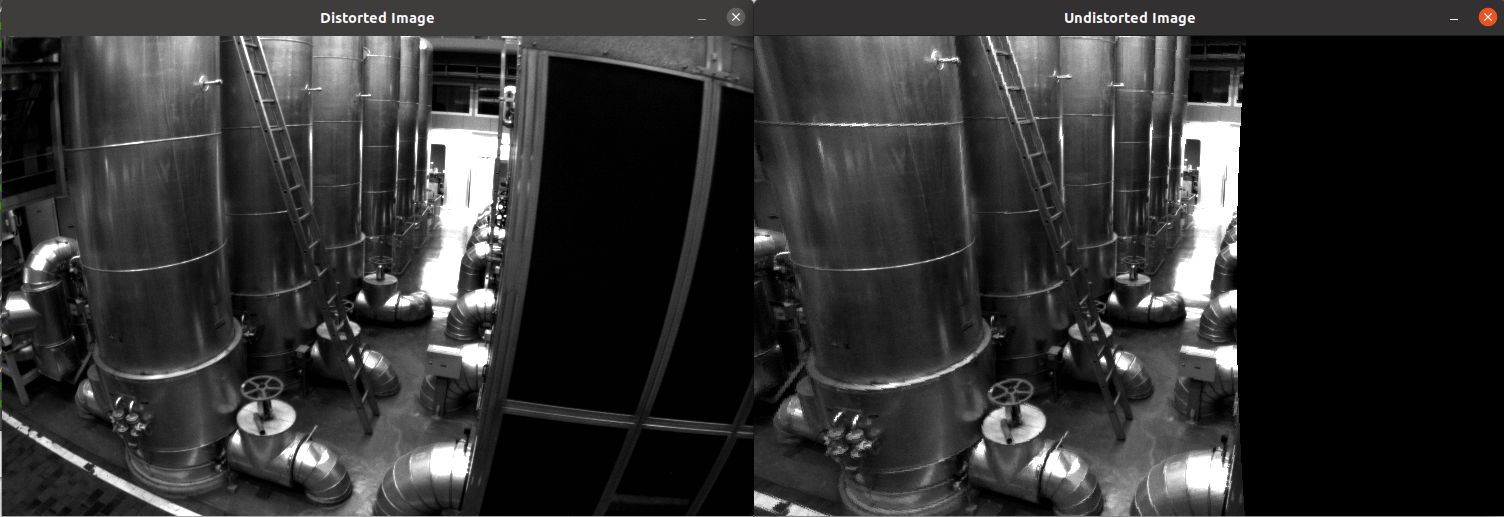
imshow("Distorted Image", image);
imshow("Undistorted Image", image_undistort);
waitKey();
return 0;
}