catalogue
1, Introduction to Ethernet communication
3.IP header checksum calculation and inspection
2, Ethernet communication example
1. Overall experimental block diagram
2. Sequence diagram of transmission part
3. Experimental code and simulation results
1, Introduction to Ethernet communication
Previously, we described a variety of communication protocols (serial port, IIC, SPI and other protocols), and Ethernet communication is a relatively high-speed communication mode. At present, Ethernet refers to the LAN composed of IEEE 802.3 standard. IEEE 802.3 standard mainly specifies the medium access control sublayer (MAC) in the physical layer (PHY) and data link layer of the reference model. To put it simply, in order to unify the communication standard, the international organization for Standardization (ISO) has formulated the OSI (Open System Interconnection) model of the whole Ethernet communication structure, which is translated into open system interconnection.
1.OSI seven layer model
OSI defines the seven layer framework of network interconnection (physical layer, data link layer, network layer, transport layer, session layer, presentation layer and application layer), that is, OSI open interconnection system reference model. Each layer has different functions and performs its own duties in network communication. The whole model includes hardware and software definitions. OSI model is only an ideal layer, and the general network system only involves several layers. The reference model and brief introduction of each layer are shown in the figure below.
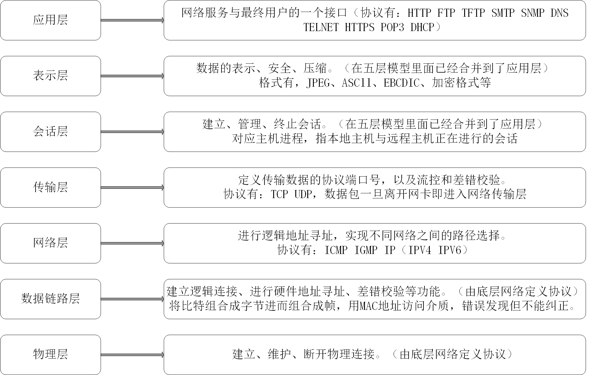
In the physical layer, the media used in Ethernet (crystal head network cable), data coding method (Manchester coding) and conflict detection mechanism (CSMA/CD conflict detection) are mainly specified. In practical application, its function is mainly realized by a PHY chip.
In the data link layer, it mainly specifies the MAC sublayer in the lower half of the data link layer, which is mainly responsible for data exchange with the physical layer, such as whether data can be sent, whether the sent data is correct, and controlling the data flow. It automatically adds some control signals to the data packets from the upper layer and gives them to the physical layer. When the receiver gets the normal data, it will automatically remove the MAC control signal and deliver the data packet to the upper layer.
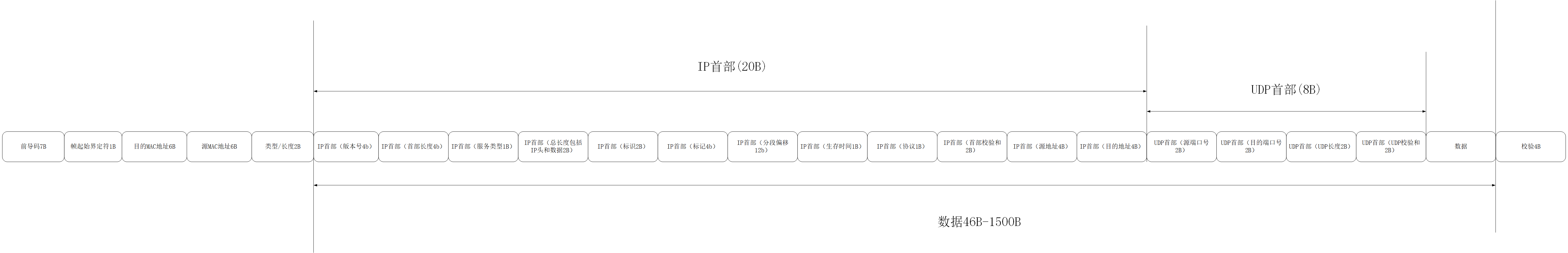
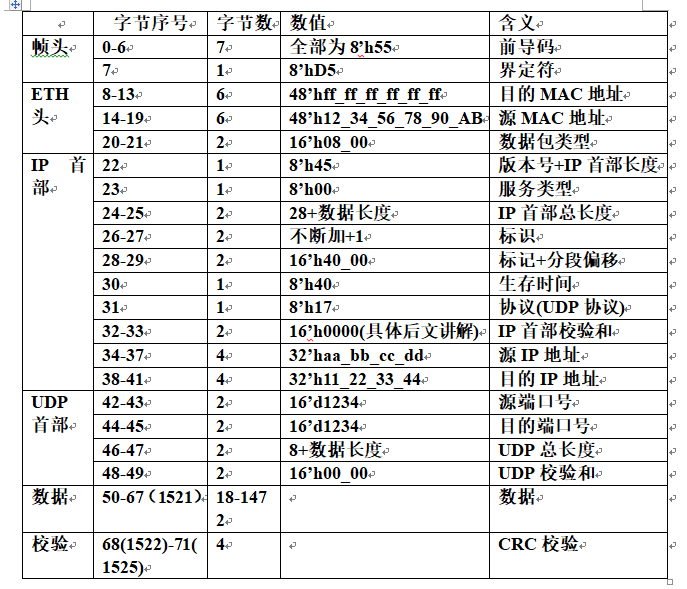
2. Ethernet packet analysis
Next, analyze a packet of data sent by Ethernet, as shown in the figure below:
3.IP header checksum calculation and inspection
The calculation method of IP header checksum in the above protocol is as follows:
IP header checksum calculation
The check byte is forcibly set to 0, and the 20 bytes of the IP header are added separately according to 2 bytes, i.e. 16 bits. If it is greater than FFFF, the high 16 bits and low 16 bits are added until the final result is 16 bit data. Invert the calculation result as the IP header checksum byte.
For example: grab the IP packet and take the header part (20B) of the IP datagram. The data is as follows: 45 00 00 30 80 4c 40 00 80 06 b5 2e d3 43 11 7b cb 51 15 3d, and calculate the IP header checksum.
(1) set the checksum field b5 2e to 00 00, and the data becomes:
45 00 00 30 80 4c 40 00 80 06 00 00 d3 43 11 7b cb 51 15 3d
(2) data inverse code summation in 2 bytes:
4500+0030+804c+4000+8006+0000+d343+117b+cb51+153d=34ace
(3) add carry (3) to the lower 16 bits (4ace):
0003+4ace=4ad1
(4) invert 4ad1 to get: checksum = b52e
Sum the binary inverse code for each 16 bit in the IP header, and take the inverse code for the calculation result. If the result is 0, it passes the test, otherwise, it does not pass the test.
Example: verify IP header 45 00 00 30 80 4c 40 00 80 06 b5 2e d3 43 11 7b cb 51 15 3d
(1) reverse code summation of IP header:
4500+0030+804c+4000+8006+b52e+d343+117b+cb51+153d=3fffc
0003+fffc=ffff
(2) inverse code of summation result:
Verify that ffff=0 is correct.
For the cyclic redundancy code check (CRC) check in the above protocol, please refer to the CRC CRC check explained in the FPGA class of V3 College - teacher you Tencent from the introduction to the last class of actual combat. Personally, I feel that the explanation is very good and suitable for beginners.
2, Ethernet communication example
Requirements: FPGA collects all experimental data, packages all data, and uploads them to the upper computer through the network port for data analysis. This experiment only completes the process of communication between FPGA and host computer through network port.
1. Overall experimental block diagram
The experimental block diagram of the whole system is given below:
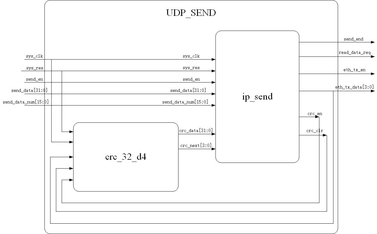
Input signal: sys_clk, which is obtained by dividing the frequency of the incoming clock (eth_clk) from the external PHY chip;
sys_res, input by external reset button
sys_en, data transmission start signal, transmitted from outside
send_data, data to be sent, imported from outside
2. Sequence diagram of transmission part
3. Experimental code and simulation results
The experimental code is given below:
1. Sending part
module udp_send
#(
    parameter   BOARD_MAC   = 48'hFF_FF_FF_FF_FF_FF ,   //Board MAC address
    parameter   BOARD_IP    = 32'hFF_FF_FF_FF       ,   //Board IP address
    parameter   BOARD_PORT  = 16'd1234              ,   //Board port number
    parameter   PC_MAC      = 48'hFF_FF_FF_FF_FF_FF ,   //MAC address of PC
    parameter   PC_IP       = 32'hFF_FF_FF_FF       ,   //IP address of PC
    parameter   PC_PORT     = 16'd1234                  //PC port number
)
(
     input               sys_clk,
	 input               sys_res,
	 input               send_en,
	 input         [15:0]send_data,
	 input         [15:0]send_data_num,
	 input         [31:0]crc_data,
     input         [3 :0]crc_next,
	 output   reg        send_end,
	 output   reg        read_data_req,
	 output   reg        eth_tx_en,
	 output   reg  [3 :0]eth_tx_data,
	 output   reg        crc_en,
	 output   reg        crc_clr
);

parameter     IDLE = 10'b0000_0000_01;
parameter     IP_HEAD_CHECK_SUM = 10'b0000_0000_10;   //Verify the 20 bytes of the IP header
parameter     PACK_HEAD = 10'b0000_0001_00;           //Send preamble and frame start delimiter
parameter     ETH_HEAD = 10'b0000_0010_00;            //Sending destination MAC address, source MAC address and type
parameter     IP_HEAD = 10'b0000_0100_00;             //Send IP header 20 bytes
parameter     UDP_HEAD = 10'b0000_1000_00;            //Send UDP header 8 bytes
parameter     DATA = 10'b0001_0000_00;
parameter     CRC = 10'b0010_0000_00;

localparam    ETH_TYPE    =   16'h0800    ;    //Protocol type IP protocol

reg     [7 :0]   mem_packet_head [7 :0];   //packet header
reg     [7 :0]   mem_eth_head    [13:0];   //Ethernet header includes destination MAC address, source MAC address and type
reg     [15:0]   mem_ip_head     [9 :0];   //IP header
reg     [15:0]   mem_udp_head    [3 :0];   //UDP header
wire     [15:0]   reg_send_data;
reg     [31:0]   ip_head_check;

reg      [9:0]stata ;
reg      [7:0]cnt   ;//Send count (count plus 1 represents one byte)
reg      [7:0]cnt_4b;//Counting plus 1 represents 4 bits
reg      [1:0]cnt_check;//ip header checksum counts for 4 times in total. Sum 20 bytes in the first count, add the high 16 bits to the low 16 bits in the second count, repeat the last operation in the third count, and reverse the fourth count
reg      [11:0]cnt_add;
wire     [15:0]data_num_add; //If the number of transmissions does not meet 46, the transmission data needs to be supplemented
reg      flag;

reg           reg_send_en;
wire          rise_send_en;
//Get send_ Rising edge of EN
assign        rise_send_en = send_en & (~reg_send_en);
always@(posedge sys_clk or negedge sys_res)
    if(!sys_res)
	   reg_send_en <= 1'b0;
	else
	   reg_send_en <= send_en;
//Judge whether the transmitted data meets the minimum 46 requirements
assign  data_num_add = (send_data_num<23)?23:send_data_num;

always@(posedge sys_clk or negedge sys_res)
    if(!sys_res)
	   cnt_add <= 'd0;
	else if(stata == DATA && cnt_4b == 'd3 && cnt_add == send_data_num)
	   cnt_add <= 'd0;
	else if((stata == DATA && cnt_4b == 'd3 && cnt_add != 'd0)||(stata == UDP_HEAD && cnt == (8/2-1) && cnt_4b == 'd3))
	   cnt_add <= cnt_add + 1;
	else
	   cnt_add <= cnt_add;
assign  reg_send_data = (cnt_add == 0)? 16'd0:send_data;


//IP_HEAD_CHECK_SUM(IP header checksum)
always@(posedge sys_clk or negedge sys_res)
    if(!sys_res)
       	cnt_check  <= 'd0;
    else if(stata == IP_HEAD_CHECK_SUM)
	    cnt_check  <= cnt_check + 1'b1;
	else if(stata != IP_HEAD_CHECK_SUM)
	    cnt_check  <= 'd0;
    else
        cnt_check  <= cnt_check;
always@(posedge sys_clk or negedge sys_res)
    if(!sys_res)
	    ip_head_check <= 'd0;
    else if(stata == IP_HEAD_CHECK_SUM && cnt_check == 'd0)
	    ip_head_check <= mem_ip_head[0] + mem_ip_head[1] + mem_ip_head[2] + mem_ip_head[3] +
		                 mem_ip_head[4] + mem_ip_head[5] + mem_ip_head[6] + mem_ip_head[7] +
						 mem_ip_head[8] + mem_ip_head[9];
	else if(stata == IP_HEAD_CHECK_SUM && cnt_check == 'd1)
	    ip_head_check <= ip_head_check[31:16]+ ip_head_check[15:0];
	else if(stata == IP_HEAD_CHECK_SUM && cnt_check == 'd2)
	    ip_head_check <= ip_head_check[31:16]+ ip_head_check[15:0];
	else
	    ip_head_check <= ip_head_check;

//PACK_HEAD includes 7 8'h55 and 1 8'hd5
always@(posedge sys_clk or negedge sys_res)
    if(!sys_res)begin
        mem_packet_head[0]  <=  8'h00;
		mem_packet_head[1]  <=  8'h00;
		mem_packet_head[2]  <=  8'h00;
		mem_packet_head[3]  <=  8'h00;
		mem_packet_head[4]  <=  8'h00;
		mem_packet_head[5]  <=  8'h00;
		mem_packet_head[6]  <=  8'h00;
		mem_packet_head[7]  <=  8'h00;
    end
	else begin
	    mem_packet_head[0]  <=  8'h55;
		mem_packet_head[1]  <=  8'h55;
		mem_packet_head[2]  <=  8'h55;
		mem_packet_head[3]  <=  8'h55;
		mem_packet_head[4]  <=  8'h55;
		mem_packet_head[5]  <=  8'h55;
		mem_packet_head[6]  <=  8'h55;
		mem_packet_head[7]  <=  8'hd5;
	end
//ETH_HEAD includes destination MAC address, source MAC address and type
always@(posedge sys_clk or negedge sys_res)
    if(!sys_res)begin
	    mem_eth_head[0]  <= 8'h00;
		mem_eth_head[1]  <= 8'h00;
		mem_eth_head[2]  <= 8'h00;
		mem_eth_head[3]  <= 8'h00;
		mem_eth_head[4]  <= 8'h00;
		mem_eth_head[5]  <= 8'h00;
		mem_eth_head[6]  <= 8'h00;
		mem_eth_head[7]  <= 8'h00;
		mem_eth_head[8]  <= 8'h00;
		mem_eth_head[9]  <= 8'h00;
		mem_eth_head[10] <= 8'h00;
		mem_eth_head[11] <= 8'h00;
		mem_eth_head[12] <= 8'h00;
		mem_eth_head[13] <= 8'h00;
	end
	else begin
	    mem_eth_head[0]  <=    PC_MAC     [47:40]      ;
		mem_eth_head[1]  <=    PC_MAC     [39:32]      ;
		mem_eth_head[2]  <=    PC_MAC     [31:24]      ;
		mem_eth_head[3]  <=    PC_MAC     [23:16]      ;
		mem_eth_head[4]  <=    PC_MAC     [15:8 ]      ;
		mem_eth_head[5]  <=    PC_MAC     [7 :0 ]      ;
		mem_eth_head[6]  <=    BOARD_MAC  [47:40]      ;
		mem_eth_head[7]  <=    BOARD_MAC  [39:32]      ;
		mem_eth_head[8]  <=    BOARD_MAC  [31:24]      ;
		mem_eth_head[9]  <=    BOARD_MAC  [23:16]      ;
		mem_eth_head[10] <=    BOARD_MAC  [15:8 ]      ;
		mem_eth_head[11] <=    BOARD_MAC  [7 :0 ]      ;
		mem_eth_head[12] <=    ETH_TYPE   [15:8 ]      ;
		mem_eth_head[13] <=    ETH_TYPE   [7 :0 ]      ;
	end
//IP_HEAD includes version number, header length, service type, total length, identification, mark, segment offset, lifetime, protocol, header checksum, source IP address and destination IP address
always@(posedge sys_clk or negedge sys_res)
    if(!sys_res)begin
	   mem_ip_head[0] <= 'd0;
	   mem_ip_head[1] <= 'd0;
	   mem_ip_head[2] <= 'd0;
	   mem_ip_head[3] <= 'd0;
	   mem_ip_head[4] <= 'd0;
	   mem_ip_head[5] <= 'd0;
	   mem_ip_head[6] <= 'd0;
	   mem_ip_head[7] <= 'd0;
	   mem_ip_head[8] <= 'd0;
	   mem_ip_head[9] <= 'd0;
	end
    else if(stata == IDLE && rise_send_en == 1'b1)begin
	   mem_ip_head[0] <= {4'h4,4'h5,8'h00} ;//Version number 4; Head length 5; Service type 0
	   mem_ip_head[1] <=  28+send_data_num*2 ;
	   mem_ip_head[2] <=  mem_ip_head[2]+1 ;
	   mem_ip_head[3] <= {3'b010,13'b0_0000_0000_0000} ;//Mark 010; The segment offset is 0
	   mem_ip_head[4] <= {8'h40,8'h17}  ;//Survival time 40; Agreement 17
	   mem_ip_head[5] <= 16'h00_00      ;//The initial checksum is 0
	   mem_ip_head[6] <=  BOARD_IP[32:16]    ;
	   mem_ip_head[7] <=  BOARD_IP[15: 0]    ;
	   mem_ip_head[8] <=  PC_IP[32:16]       ;
	   mem_ip_head[9] <=  PC_IP[15: 0]       ;
	end
	else if(stata == IP_HEAD_CHECK_SUM && cnt_check == 'd3)begin
	   mem_ip_head[5] <=    ~ip_head_check[15:0]    ;
	end
//UDP_HEAD includes source port number, destination port number, UDP length and UDP checksum
always@(posedge sys_clk or negedge sys_res)
    if(!sys_res)begin
	   mem_udp_head[0] <= 'd0;
	   mem_udp_head[1] <= 'd0;
	   mem_udp_head[2] <= 'd0;
	   mem_udp_head[3] <= 'd0;
	end
	else begin
       mem_udp_head[0] <= BOARD_PORT;
	   mem_udp_head[1] <= PC_PORT;
	   mem_udp_head[2] <= send_data_num*2+8 ;
	   mem_udp_head[3] <= 16'h0000 ;    //udp checksum is 0
	end


always@(posedge sys_clk or negedge sys_res)
    if(!sys_res)
	   cnt_4b <= 'd0;
	else if(stata == PACK_HEAD || stata == ETH_HEAD )
	   if(cnt_4b == 'd1)
	      cnt_4b <= 'd0;
       else
	      cnt_4b <= cnt_4b + 1;
	else if(stata == IP_HEAD || stata == UDP_HEAD || stata == DATA)
	   if(cnt_4b == 'd3)
	      cnt_4b <= 'd0;
       else
	      cnt_4b <= cnt_4b + 1;
	else if(stata == CRC)
	   if(cnt_4b == 'd7)
	      cnt_4b <= 'd0;
       else
	      cnt_4b <= cnt_4b + 1;
	else
	   cnt_4b <= 'd0;

always@(posedge sys_clk or negedge sys_res)
    if(!sys_res)
	   cnt    <= 'd0;
	else if( stata == PACK_HEAD )begin
       if(cnt == 8-1 && cnt_4b == 1'b1)
	      cnt <= 'd0;
	   else if(cnt_4b == 1'b1)
	      cnt <= cnt + 1;
	   else
	      cnt <= cnt;
	end
	else if( stata == ETH_HEAD )begin
       if(cnt == 14-1 && cnt_4b == 1'b1)
	      cnt <= 'd0;
	   else if(cnt_4b == 1'b1)
	      cnt <= cnt + 1;
	   else
	      cnt <= cnt;
	end
	else if( stata == IP_HEAD )begin
       if(cnt == (20/2-1) && cnt_4b == 'd3)
	      cnt <= 'd0;
	   else if(cnt_4b == 'd3)
	      cnt <= cnt + 1;
	   else
	      cnt <= cnt;
	end
	else if( stata == UDP_HEAD )begin
       if(cnt == (8/2-1) && cnt_4b == 'd3)
	      cnt <= 'd0;
	   else if(cnt_4b == 'd3)
	      cnt <= cnt + 1;
	   else
	      cnt <= cnt;
	end
    else if( stata == DATA )begin
       if((cnt == (data_num_add-1)) && cnt_4b == 'd3)
	      cnt <= 'd0;
	   else if(cnt_4b == 'd3)
	      cnt <= cnt + 1;
	   else
	      cnt <= cnt;
	end
    else if( stata == CRC )begin
       if((cnt == (4/4-1)) && cnt_4b == 'd7)
	      cnt <= 'd0;
	   else if(cnt_4b == 'd7)
	      cnt <= cnt + 1;
	   else
	      cnt <= cnt;
	end
    else
	   cnt <= 'd0;


//State machine
always@(posedge sys_clk or negedge sys_res)
    if(!sys_res)
       stata <= IDLE;
    else begin
	   case(stata)
	       IDLE:                  if(rise_send_en == 1'b1)
		                             stata <= IP_HEAD_CHECK_SUM;
				                  else
				                     stata <= IDLE;
		   IP_HEAD_CHECK_SUM:     if(cnt_check == 3)
		                             stata <= PACK_HEAD;
				                  else
				                     stata <= IP_HEAD_CHECK_SUM;
		   PACK_HEAD:             if(cnt == 8-1 && cnt_4b == 1'b1)
		                             stata <= ETH_HEAD;
								  else
								     stata <= PACK_HEAD;
		   ETH_HEAD:			  if(cnt == 14-1 && cnt_4b == 1'b1)
		                             stata <= IP_HEAD;
								  else
								     stata <= ETH_HEAD;
		   IP_HEAD:               if(cnt == (20/2-1) && cnt_4b == 'd3)
		                             stata <= UDP_HEAD;
								  else
								     stata <= IP_HEAD;
		   UDP_HEAD:              if(cnt == (8/2-1) && cnt_4b == 'd3)
		                             stata <= DATA;
								  else
								     stata <= UDP_HEAD;
		   DATA:                  if(cnt == (data_num_add-1) && cnt_4b == 'd3)
		                             stata <= CRC;
								  else
								     stata <= DATA;
		   CRC:                   if(cnt == (4/4-1) && cnt_4b == 'd7)
		                             stata <= IDLE;
								  else
								     stata <= CRC;
		   default:stata <= IDLE;
	   endcase
    end

//Signal output eth_tx_data,eth_tx_en
always@(posedge sys_clk or negedge sys_res)
    if(!sys_res)
	    eth_tx_en <= 1'b0;
	else if(stata == PACK_HEAD || stata == ETH_HEAD || stata == IP_HEAD || stata == UDP_HEAD || stata == DATA || stata == CRC)
	    eth_tx_en <= 1'b1;
	else
	    eth_tx_en <= 1'b0;
always@(posedge sys_clk or negedge sys_res)
    if(!sys_res)	begin
	    flag <= 1'b0;
        eth_tx_data <= 'd0;
	end
    else if(stata == PACK_HEAD)
        if(cnt_4b == 0)
            eth_tx_data <= mem_packet_head[cnt][7:4];
        else
		    eth_tx_data <= mem_packet_head[cnt][3:0];
    else if(stata == ETH_HEAD)
        if(cnt_4b == 0)
            eth_tx_data <= mem_eth_head[cnt][7:4];
        else
		    eth_tx_data <= mem_eth_head[cnt][3:0];
    else if(stata == IP_HEAD)begin
        if(cnt_4b == 0)
            eth_tx_data <= mem_ip_head[cnt][15:12];
        else if(cnt_4b == 1)
		    eth_tx_data <= mem_ip_head[cnt][11:8];
        else if(cnt_4b == 2)
		    eth_tx_data <= mem_ip_head[cnt][7:4];
		else if(cnt_4b == 3)
            eth_tx_data <= mem_ip_head[cnt][3:0];
	end
    else if(stata == UDP_HEAD)begin
	    flag <= 1'b1;
        if(cnt_4b == 0)	begin

			eth_tx_data <= mem_udp_head[cnt][15:12];
	    end
        else if(cnt_4b == 1)
		    eth_tx_data <= mem_udp_head[cnt][11:8];
        else if(cnt_4b == 2)
		    eth_tx_data <= mem_udp_head[cnt][7:4];
		else if(cnt_4b == 3)begin

			eth_tx_data <= mem_ip_head[cnt][3:0];
		end
	end
    else if(stata == DATA)begin
	    flag <= 1'b0;
        if(cnt_4b == 0)
            eth_tx_data <= reg_send_data[15:12];
        else if(cnt_4b == 1)
		    eth_tx_data <= reg_send_data[11:8];
        else if(cnt_4b == 2)
		    eth_tx_data <= reg_send_data[7:4];
		else if(cnt_4b == 3)
            eth_tx_data <= reg_send_data[3:0];
	end
    else if(stata == CRC)begin
        if(cnt_4b == 0)
            eth_tx_data <= {~crc_next[0], ~crc_next[1], ~crc_next[2], ~crc_next[3]};
        else if(cnt_4b == 1)
		    eth_tx_data <=  {~crc_data[24],~crc_data[25],~crc_data[26],~crc_data[27]};
        else if(cnt_4b == 2)
		    eth_tx_data <=  {~crc_data[20],~crc_data[21],~crc_data[22],~crc_data[23]};
		else if(cnt_4b == 3)
            eth_tx_data <=  {~crc_data[16],~crc_data[17],~crc_data[18],~crc_data[19]};
		else if(cnt_4b == 4)
		    eth_tx_data <=  {~crc_data[12],~crc_data[13],~crc_data[14],~crc_data[15]};
        else if(cnt_4b == 5)
		    eth_tx_data <=  {~crc_data[8],~crc_data[9],~crc_data[10],~crc_data[11]};
		else if(cnt_4b == 6)
            eth_tx_data <=  {~crc_data[4],~crc_data[5],~crc_data[6],~crc_data[7]};
		else if(cnt_4b == 7)
            eth_tx_data <=  {~crc_data[0],~crc_data[1],~crc_data[2],~crc_data[3]};
    end
    else
	    eth_tx_data <= eth_tx_data;


//Signal output send_end
always@(posedge sys_clk or negedge sys_res)
    if(!sys_res)
	    send_end <= 1'b0;
	else if(stata == CRC && cnt == (4/4-1) && cnt_4b == 'd7)
	    send_end <= 1'b1;
	else
	    send_end <= 1'b0;
//Output signal read_data_req
always@(posedge sys_clk or negedge sys_res)
    if(!sys_res)
       read_data_req <= 1'b0;
    else if((stata == UDP_HEAD && cnt == (8/2-1) && cnt_4b == 'd3)||(stata == DATA && cnt_4b == 'd3))
	   read_data_req <= 1'b1;
	else
	   read_data_req <= 1'b0;

//Output crc signal_ en
always@(posedge sys_clk or negedge sys_res)
    if(!sys_res)
      	crc_en <= 1'b0;
    else if(stata == ETH_HEAD || stata == IP_HEAD || stata == UDP_HEAD || stata == DATA)
        crc_en <= 1'b1;
	else
	    crc_en <= 1'b0;

//Output crc signal_ clr
always@(posedge sys_clk or negedge sys_res)
    if(!sys_res)
	   crc_clr <= 1'b0;
	else
	   crc_clr <= send_end;

endmodule
2.CRC cyclic redundancy check (this part of the code copies the CRC check code in the Ethernet data exchange experiment in ZhengTu Pro FPGA Verilog development practice guide - based on Altera EP4CE10 2020.12.16 (Part 2))
`timescale  1ns/1ns

// Author        : EmbedFire
// Create Date   : 2019/09/03
// Module Name   : crc32_d4
// Project Name  : eth_udp_rmii
// Target Devices: Altera EP4CE10F17C8N
// Tool Versions : Quartus 13.0
// Description: CRC verification
//
// Revision      : V1.0
// Additional Comments:
//
// Experimental platform: Wildfire_ Journey Pro_FPGA development board
// Company: http://www.embedfire.com
// Forum: http://www.firebbs.cn
// TaoBao: https://fire-stm32.taobao.com


module  crc32_d4
(
    input   wire            sys_clk     ,   //clock signal
    input   wire            sys_rst_n   ,   //Reset signal, active at low level
    input   wire    [3:0]   data        ,   //Data to be verified
    input   wire            crc_en      ,   //crc enable, check start flag
    input   wire            crc_clr     ,   //crc data reset signal

    output  reg     [31:0]  crc_data    ,   //CRC check data
    output  reg     [31:0]  crc_next        //CRC next verification completion data
);

//********************************************************************//
//****************** Parameter and Internal Signal *******************//
//********************************************************************//
// wire     define
wire    [3:0]   data_sw;    //The high and low bits of the data to be verified are exchanged

//********************************************************************//
//***************************** Main Code ****************************//
//********************************************************************//

//data_sw: high and low bits of data to be verified are exchanged
assign  data_sw = {data[0],data[1],data[2],data[3]};

//crc_next:CRC next verification completion data
//The generating polynomial of CRC32 is: G(x)= x^32 + x^26 + x^23 + x^22 + x^16 + x^12 + x^11
//+ x^10 + x^8 + x^7 + x^5 + x^4 + x^2 + x^1 + 1
always@(*)
begin
    crc_next    <=  32'b0;
    if(crc_en == 1'b1)
        begin
            crc_next[0] <=  (data_sw[0] ^ crc_data[28]);
            crc_next[1] <=  (data_sw[1] ^ data_sw[0] ^ crc_data[28]
                            ^ crc_data[29]);
            crc_next[2] <=  (data_sw[2] ^ data_sw[1] ^ data_sw[0]
                            ^ crc_data[28] ^ crc_data[29] ^ crc_data[30]);
            crc_next[3] <=  (data_sw[3] ^ data_sw[2] ^ data_sw[1]
                            ^ crc_data[29] ^ crc_data[30] ^ crc_data[31]);
            crc_next[4] <=  (data_sw[3] ^ data_sw[2] ^ data_sw[0] ^ crc_data[28]
                            ^ crc_data[30] ^ crc_data[31]) ^ crc_data[0];
            crc_next[5] <=  (data_sw[3] ^ data_sw[1] ^ data_sw[0] ^ crc_data[28]
                            ^ crc_data[29] ^ crc_data[31]) ^ crc_data[1];
            crc_next[6] <=  (data_sw[2] ^ data_sw[1] ^ crc_data[29]
                            ^ crc_data[30]) ^ crc_data[ 2];
            crc_next[7] <=  (data_sw[3] ^ data_sw[2] ^ data_sw[0] ^ crc_data[28]
                            ^ crc_data[30] ^ crc_data[31]) ^ crc_data[3];
            crc_next[8] <=  (data_sw[3] ^ data_sw[1] ^ data_sw[0] ^ crc_data[28]
                            ^ crc_data[29] ^ crc_data[31]) ^ crc_data[4];
            crc_next[9] <=  (data_sw[2] ^ data_sw[1] ^ crc_data[29]
                            ^ crc_data[30]) ^ crc_data[5];
            crc_next[10]<=  (data_sw[3] ^ data_sw[2] ^ data_sw[0] ^ crc_data[28]
                            ^ crc_data[30] ^ crc_data[31]) ^ crc_data[6];
            crc_next[11]<=  (data_sw[3] ^ data_sw[1] ^ data_sw[0] ^ crc_data[28]
                            ^ crc_data[29] ^ crc_data[31]) ^ crc_data[7];
            crc_next[12]<=  (data_sw[2] ^ data_sw[1] ^ data_sw[0] ^ crc_data[28]
                            ^ crc_data[29] ^ crc_data[30]) ^ crc_data[8];
            crc_next[13]<=  (data_sw[3] ^ data_sw[2] ^ data_sw[1] ^ crc_data[29]
                                ^ crc_data[30] ^ crc_data[31]) ^ crc_data[9];
            crc_next[14]<=  (data_sw[3] ^ data_sw[2] ^ crc_data[30]
                            ^ crc_data[31]) ^ crc_data[10];
            crc_next[15]<=  (data_sw[3] ^ crc_data[31]) ^ crc_data[11];
            crc_next[16]<=  (data_sw[0] ^ crc_data[28]) ^ crc_data[12];
            crc_next[17]<=  (data_sw[1] ^ crc_data[29]) ^ crc_data[13];
            crc_next[18]<=  (data_sw[2] ^ crc_data[30]) ^ crc_data[14];
            crc_next[19]<=  (data_sw[3] ^ crc_data[31]) ^ crc_data[15];
            crc_next[20]<=  crc_data[16];
            crc_next[21]<=  crc_data[17];
            crc_next[22]<=  (data_sw[0] ^ crc_data[28]) ^ crc_data[18];
            crc_next[23]<=  (data_sw[1] ^ data_sw[0] ^ crc_data[29]
                            ^ crc_data[28]) ^ crc_data[19];
            crc_next[24]<=  (data_sw[2] ^ data_sw[1] ^ crc_data[30]
                            ^ crc_data[29]) ^ crc_data[20];
            crc_next[25]<=  (data_sw[3] ^ data_sw[2] ^ crc_data[31]
                            ^ crc_data[30]) ^ crc_data[21];
            crc_next[26]<=  (data_sw[3] ^ data_sw[0] ^ crc_data[31]
                            ^ crc_data[28]) ^ crc_data[22];
            crc_next[27]<=  (data_sw[1] ^ crc_data[29]) ^ crc_data[23];
            crc_next[28]<=  (data_sw[2] ^ crc_data[30]) ^ crc_data[24];
            crc_next[29]<=  (data_sw[3] ^ crc_data[31]) ^ crc_data[25];
            crc_next[30]<=  crc_data[26];
            crc_next[31]<=  crc_data[27];
        end
end

//crc_data:CRC verification data
always @(posedge sys_clk or negedge sys_rst_n)
    if(sys_rst_n == 1'b0)
        crc_data    <=  32'hff_ff_ff_ff;
    else if(crc_clr == 1'b1)
        crc_data    <= 32'hff_ff_ff_ff;
    else if(crc_en == 1'b1)
        crc_data    <=  crc_next;

endmodule
3. The top layer and simulation tb files are given below. In order to facilitate the simulation observation of timing, the two parts are combined into the following code
`timescale 1ns/1ns
module tb_udp_send();
reg clk;
reg res;
reg send_en;
reg [15:0]send_data;
wire [15:0]send_data_num;
wire send_end;
wire read_data_req;
wire eth_tx_en;
wire [3:0]eth_tx_data;
wire crc_en;
wire crc_clr;
wire [31:0]crc_data;
wire [31:0]crc_next;
parameter BOARD_MAC = 48'hFF_FF_FF_FF_FF_FF;
parameter BOARD_IP = 32'hFF_FF_FF_FF;
parameter BOARD_PORT = 16'd1234 ;
parameter PC_MAC = 48'hFF_FF_FF_FF_FF_FF;
parameter PC_IP = 32'hFF_FF_FF_FF ;
parameter PC_PORT = 16'd1234 ;
parameter NUM = 10;
reg [15:0]mem_data[9:0];
reg [7:0]cnt;
reg reg_rd_req;
wire rise_req;
initial begin
clk <= 1'b0;
res <= 1'b0;
send_en <= 1'b0;
send_data <= 16'd0;
reg_rd_req <= 1'b0;
#100 res <= 1'b1;
#1000 send_en <= 1'b1;
#500 send_en <= 1'b0;
end
always #10 clk <= ~clk;
//Send data and store it in MEM_ In data
always@(posedge clk or negedge clk)
if(!res)begin
mem_data[0] <= 0;
mem_data[1] <= 0;
mem_data[2] <= 0;
mem_data[3] <= 0;
mem_data[4] <= 0;
mem_data[5] <= 0;
mem_data[6] <= 0;
mem_data[7] <= 0;
mem_data[8] <= 0;
mem_data[9] <= 0;
end
else begin
mem_data[0] <= 16'h1111;
mem_data[1] <= 16'h1234;
mem_data[2] <= 16'h5678;
mem_data[3] <= 16'h9abc;
mem_data[4] <= 16'hdef0;
mem_data[5] <= 16'h1234;
mem_data[6] <= 16'h5678;
mem_data[7] <= 16'h9abc;
mem_data[8] <= 16'hdef0;
mem_data[9] <= 16'haaaa;
end
assign send_data_num = NUM;
always@(clk)
reg_rd_req <= read_data_req;
assign rise_req = (~reg_rd_req)&read_data_req;
always@(posedge clk or negedge clk)
if(!res)
cnt <= 'd0;
else if(rise_req && cnt == NUM-1)
cnt <= 'd0;
else if(rise_req)
cnt <= cnt + 1 ;
else
cnt <= cnt;
always@(clk)
if(rise_req)
send_data <= mem_data[cnt];
else
send_data <= send_data;
udp_send
#(
. BOARD_MAC (BOARD_MAC) , //Board MAC address
. BOARD_IP (BOARD_IP) , //Board IP address
. BOARD_PORT (BOARD_PORT) , //Board port number
. PC_MAC (PC_MAC) , //MAC address of PC
. PC_IP (PC_IP) , //IP address of PC
. PC_PORT (PC_PORT) //PC port number
)u_udp_send
(
.sys_clk (clk) ,
.sys_res (res) ,
.send_en (send_en) ,
.send_data (send_data) ,
.send_data_num (send_data_num) ,
.crc_data (crc_data) ,
.crc_next (crc_next[31:28]) ,
.send_end (send_end) ,
.read_data_req (read_data_req) ,
.eth_tx_en (eth_tx_en) ,
.eth_tx_data (eth_tx_data) ,
.crc_en (crc_en) ,
.crc_clr (crc_clr)
);
crc32_d4 u_crc32_d4
(
. sys_clk (clk) , //clock signal
. sys_rst_n (res) , //Reset signal, active at low level
. data (eth_tx_data), //Data to be verified
. crc_en (crc_en) , //crc enable, check start flag
. crc_clr (crc_clr), //crc data reset signal
. crc_data (crc_data), //CRC check data
. crc_next (crc_next) //CRC next verification completion data
);
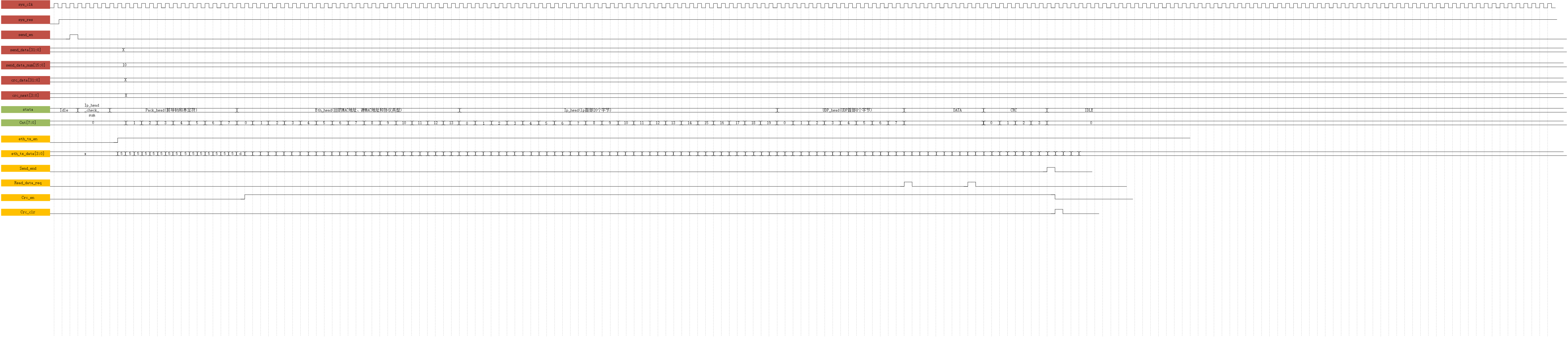
endmoduleThe following figure shows the timing results of the simulation: Figure 1 is the timing diagram of the overall signal, and Figure 2 corresponds to pack_ The signal output in the head state, figure 3 corresponds to eth_ The signal output in the head state, as shown in Figure 4, corresponds to IP_ The signal output in the head state, as shown in Figure 5, corresponds to UDP_ For the signal output in the head state, FIG. 6 corresponds to the signal output in the DATA state, and Fig. 7 corresponds to the signal output in the CRC state.
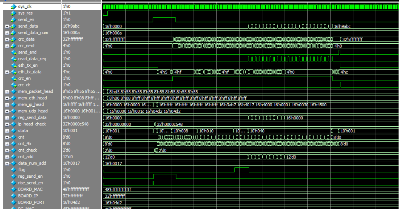
Figure 1
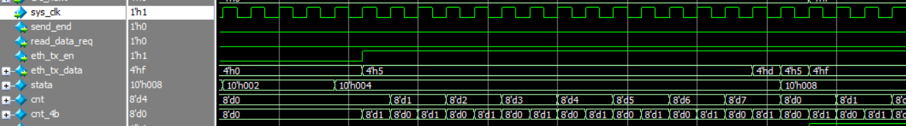
Figure 2
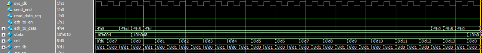
Figure 3

Figure 4
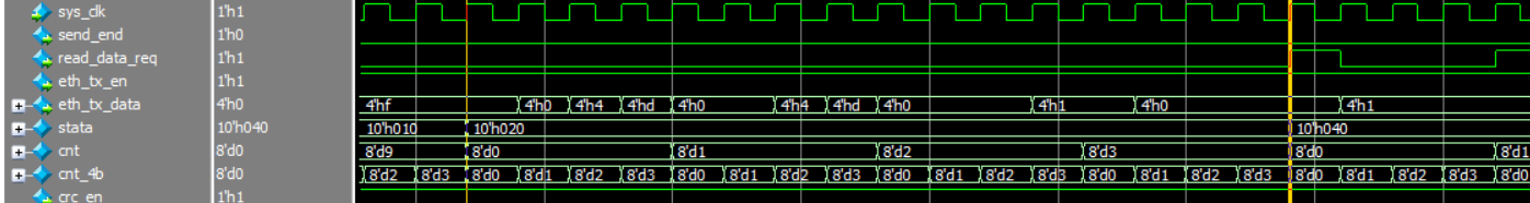
Figure 5

Figure 6
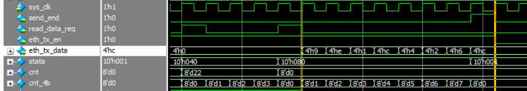 Figure 7
summary
For Ethernet communication, it still tends to be controlled by single chip microcomputer. Its program code is much simpler than Verilog. Readers can try to do this experiment. The timing logic of Ethernet communication controlled by FPGA is relatively complex. This paper only gives the timing and code of FPGA transmission through the network port. Because the epidemic is at home and there is no hardware equipment around, the program will be applied to practice in the later stage.
It is inevitable that there are errors in the article for the first time. I hope readers can correct and give private letters in time. I hope you can make progress together!