Experiment of deploying LVS-DR mode with ENSP simulator and Linux
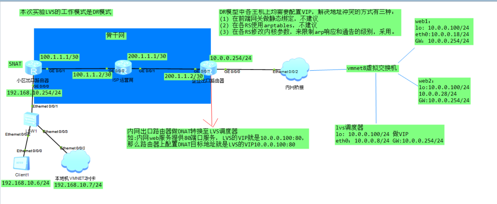
topology
environment
The customer's private network IP is 192.168.10.6/24. The gateway points to the cell exit router, which is configured with SNAT conversion. OSPF is simulated between the whole backbone network to obtain the whole network route, and the private network address is not announced into the backbone network, so there is no connection between the private network of the community and the intranet of the enterprise. The enterprise exit router is also configured with SNAT conversion to enable intranet users to access the public network.
The web server and LVS scheduler provided by the enterprise intranet are virtualized through local Vmware. The bridge is realized through the cloud device of ENSP.
step
1. SNAT configuration of cell exit Router:
acl number 2000
 rule 5 permit source 192.168.10.0 0.0.0.255

interface GigabitEthernet0/0/1
 ip address 100.1.1.1 255.255.255.252
 nat outbound 2000

ospf 10
 area 0.0.0.0
  network 100.1.1.0 0.0.0.255
2. ospf protocol is used for routing between backbone networks
#ISP operator
interface GigabitEthernet0/0/0
 ip address 100.1.1.2 255.255.255.252
#
interface GigabitEthernet0/0/1
 ip address 200.1.1.1 255.255.255.252

ospf 10
 area 0.0.0.0
  network 100.1.1.0 0.0.0.255
  network 200.1.1.0 0.0.0.255
3. Configure the enterprise exit router SNAT (enabling the enterprise intranet users to access the public network) and DNAT (providing intranet services for external network access). The DNAT address points to the VIP address of the LVS scheduler.
acl number 2000
 rule 5 permit source 10.0.1.0 0.0.0.255

ospf 10
 area 0.0.0.0
  network 200.1.1.0 0.0.0.255

interface GigabitEthernet0/0/0
 ip address 10.0.0.254 255.255.255.0
#
interface GigabitEthernet0/0/1
 ip address 200.1.1.2 255.255.255.252
 nat static protocol tcp global current-interface www inside 10.0.0.100 www netm
ask 255.255.255.255
 nat outbound 2000
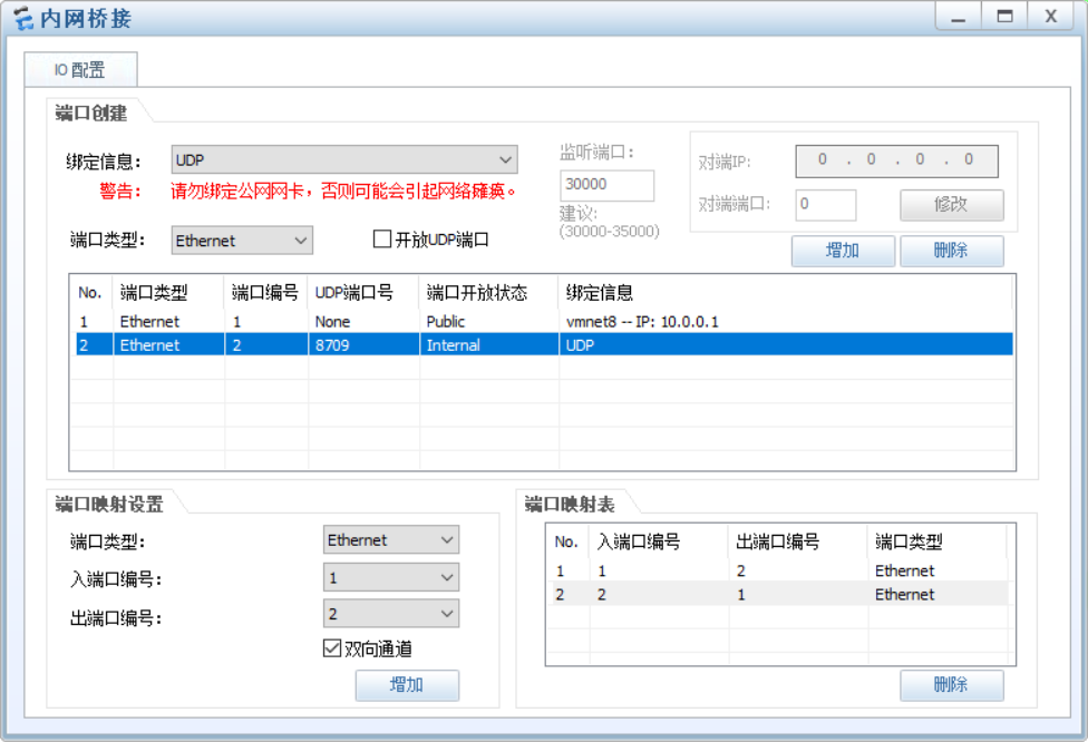
4.cloud device configuration, bridging the local virtual machine environment
5. Deploy web server
The web1 host closes the lo port arp response and broadcast, and configures the gateway to point to the exit router
[root@maple-c8-n2 ~]# ifconfig lo:1 10.0.0.100/32
[root@maple-c8-n2 ~]# echo 1 > /proc/sys/net/ipv4/conf/all/arp_ignore
[root@maple-c8-n2 ~]# echo 2 > /proc/sys/net/ipv4/conf/all/arp_announce
[root@maple-c8-n2 ~]# echo 2 > /proc/sys/net/ipv4/conf/lo/arp_announce
[root@maple-c8-n2 ~]# echo 1 > /proc/sys/net/ipv4/conf/lo/arp_ignore
[root@maple-c8-n2 ~]# sysctl -a | grep arp_announce
net.ipv4.conf.all.arp_announce = 2
net.ipv4.conf.default.arp_announce = 0
net.ipv4.conf.eth0.arp_announce = 0
net.ipv4.conf.lo.arp_announce = 2
[root@maple-c8-n2 ~]# sysctl -a | grep arp_ignore
net.ipv4.conf.all.arp_ignore = 1
net.ipv4.conf.default.arp_ignore = 0
net.ipv4.conf.eth0.arp_ignore = 0
net.ipv4.conf.lo.arp_ignore = 1

[root@maple-c8-n2 ~]# cat /etc/sysconfig/network-scripts/ifcfg-eth0
BOOTPROTO=static
NAME=eth0
DEVICE=eth0
ONBOOT=yes
IPADDR=10.0.0.18
PREFIX=24
GATEWAY=10.0.0.254

nmcli conn reload
nmcli conn up eth0
web2 host
[root@maple-c8-n3 ~]# ifconfig lo:1 10.0.0.100/32
[root@maple-c8-n3 ~]# echo 1 > /proc/sys/net/ipv4/conf/all/arp_ignore
[root@maple-c8-n3 ~]# echo 2 > /proc/sys/net/ipv4/conf/all/arp_announce
[root@maple-c8-n3 ~]# echo 2 > /proc/sys/net/ipv4/conf/lo/arp_announce
[root@maple-c8-n3 ~]# echo 1 > /proc/sys/net/ipv4/conf/lo/arp_ignore
[root@maple-c8-n3 ~]# sysctl -a | grep arp_ignore
net.ipv4.conf.all.arp_ignore = 1
net.ipv4.conf.default.arp_ignore = 0
net.ipv4.conf.eth0.arp_ignore = 0
net.ipv4.conf.lo.arp_ignore = 1
[root@maple-c8-n3 ~]#  sysctl -a | grep arp_announce
net.ipv4.conf.all.arp_announce = 2
net.ipv4.conf.default.arp_announce = 0
net.ipv4.conf.eth0.arp_announce = 0
net.ipv4.conf.lo.arp_announce = 2

[root@maple-c8-n3 ~]#  cat /etc/sysconfig/network-scripts/ifcfg-eth0
BOOTPROTO=static
NAME=eth0
DEVICE=eth0
ONBOOT=yes
IPADDR=10.0.0.28
PREFIX=24
GATEWAY=10.0.0.254

nmcli conn reload
nmcli conn up eth0
6. lvs server configuration
[root@maple-c8-n1 ~]# cat /etc/sysconfig/network-scripts/ifcfg-eth0
BOOTPROTO=static
NAME=eth0
DEVICE=eth0
ONBOOT=yes
IPADDR=10.0.0.8
GATEWAY=10.0.0.254
PREFIX=24

[root@maple-c8-n1 ~]#ifconfig lo:1 10.0.0.100/32

#Network card loading takes effect
nmcli conn reload
nmcli conn up eth0
nmcli conn up eth1

#Enable routing forwarding function
echo "net.ipv4.ip_forward=1" >> /etc/sysctl.conf
sysctl -p

#lvs configuration
 ipvsadm -A -t 10.0.0.100:80 -s rr  #Add cluster
 ipvsadm -a -t 10.0.0.100:80 -r 10.0.0.28:80 -g #Add a web node to the cluster
 ipvsadm -a -t 10.0.0.100:80 -r 10.0.0.18:80 -g

 ipvsadm -S >  /etc/sysconfig/ipvsadm  #Save rule to file
 systemctl enable --now ipvsadm
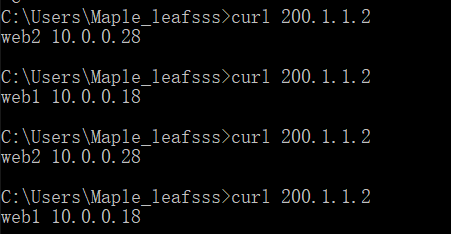
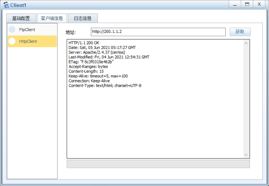
test
Different network segment configurations for VIP and DIP
The above VIP and actual ip are in the same network segment, such as VIP: 10.0.0.100 and actual ip10 0.0.8
It can also be configured into different network segments. For example, VIP: 172.16.0.100 and actual IP10 0.0.8
The rewriting steps are as follows:
web1 and web2 hosts:
ifconfig lo:1 172.16.0.100/32
lvs host:
ifconfig lo:1 172.16.0.100/32
ipvsadm -C
ipvsadm -A -t 172.16.0.100:80 -s rr
ipvsadm -a -t 172.16.0.100:80 -r 10.0.0.18:80 -g
ipvsadm -a -t 172.16.0.100:80 -r 10.0.0.28:80 -g
Enterprise exit Router:
interface GigabitEthernet0/0/0
 ip address 10.0.0.254 255.255.255.0
 ip address 172.16.0.254 255.255.255.0 sub
interface GigabitEthernet0/0/1
 ip address 200.1.1.2 255.255.255.252
 nat static protocol tcp global current-interface www inside 172.16.0.100 www netmask 255.255.255.255
 nat outbound 2000
The client test passed normally
summary
-
Both Director and RS are equipped with VIP
-
Ensure that the front-end router sends the request message with the target IP of VIP to the Director
- Statically bind the MAC addresses of VIP and Director in the front-end gateway
- Using the arptables tool on RS
- Modify kernel parameters on RS to limit arp notification and response levels
-
Port mapping is not supported (ports cannot be modified)
-
No need to turn on ip_forward
-
The RS gateway points to the exit router. The request will pass through the Director, and the response message will not pass through the Director and will be sent directly to the exit. Because each RS is configured with a VIP address.
-
RS and Director should be on the same physical network