preface
This article starts with: https://www.ebaina.com/articles/140000010059
We use the generate statement in verilog to generate code blocks conditionally or iteratively in our design.
This allows us to:
- Selectively include or exclude code blocks,
- Create multiple instantiations of a given code block.
This is very important and convenient. For the first article, we can make a module invalid or effective without deleting the code; After all, if deleted, the code structure will be destroyed, which is unfavorable to the code iteration management.
The second is even more important. For example, if you instantiate multiple modules one by one, it's OK to reduce them. If you instantiate dozens of more modules, the code will be bloated and it's almost. Use the generate statement and do it in a few lines.
The generate statement must be used correctly. It can not be used anywhere. I have written several similar blogs about this:
A foolish opinion on the usage and difference between for and generate for in Verilog
How to correctly use generate for in Verilog?
HDLBits series (7) various practices of for loop and generate for
But these articles are only aimed at the use of generate, that is, generate for. There are many other structures of generate, which will be discussed later!
generate statement of Verilog
We can only use generate statements in concurrent Verilog code blocks. This means that we cannot include it in the Always block or the initial block.
In addition, we must use the if statement, case statement or for loop with the generate keyword.
We use if and case generate statements to generate code conditionally, while for generate statements generate code iteratively.
We can write any valid verilog code we need inside the generate block. This always includes block, module instantiation, and other generate statements.
The generate block was introduced in the verilog 2001 standard. As a result, we cannot use this construct in verilog 1995 based designs.
Let's take a look at three different types of generate blocks that we can use in Verilog designs.
generate for statement in Verilog
We can use the verilog for loop within the generate block to iteratively create multiple instances of a piece of code.
We usually use the generate for loop method to describe hardware with regular and repetitive structures.
For example, we may want to describe multiple RAM modules controlled by a single bus.
If we use generate blocks instead of manually instantiating all modules, we can reduce code overhead.
The following code snippet shows the general syntax of the generate for block in verilog.
// Declare the loop variable

genvar <name>;


// Code for the

generate

  for (<initial_condition>; <stop_condition>; <increment>) begin

    // Code to execute

  end

endgenerate
From this example, we can see that the syntax of this method is actually the same as that we saw in the verilog for loop.
However, there are two important differences between this method and the conventional for loop.
-
First, we must declare the loop variable with genvar type.
-
The second difference is that we declare loops in the generate block, rather than in regular program blocks (such as the verilog always block).
This difference is important because it changes the basic behavior of the code.
-
When we write generate for blocks, we are actually telling the Verilog compiler to create multiple instances of code blocks.
-
In contrast, when we use a normal for loop, we tell the Verilog compiler to create a single instance of the code block, but execute it multiple times.
As an example, let's look at a very simple use case where we want to assign data to a 2-bit vector.
The following Verilog code shows how to do this using the generate for and for loops. In both cases, the function of the code is the same, but the resulting structure is very different.
// Example using the for loop

always @(posedge clock) begin

  for (i = 0; i < 2; i = i + 1) begin

    sig_a[i] = 1'b0;

  end

end
// Example using the generate for block

generate
1
  for (i = 0; i < 2; i = i + 1) begin
1
    always @(posedge clock) begin
1
      sig_a[i] = 1'b0;

    end

  end

endgenerate
If we expand the for loop example, we will get the following code.
always @(posedge clock) begin

  sig_a[0] = 1'b0;

  sig_a[1] = 1'b0;

end
Instead, the generation of expansion code will result in the following code.
always @(posedge clock) begin

  sig_a[0] = 1'b0;

end


always @(posedge clock) begin

  sig_a[1] = 1'b0;

end
This shows the essential difference between for generation and for loop.
Verilog generate for example
To better illustrate how verilog generates for statements, let's consider a basic example.
In this example, we will use an array of three RAM modules connected to the same bus.
Each RAM module has a write enable port, a 4-bit address input and a 4-bit data input. These signals are connected to the same bus.
In addition, each RAM has a 4-bit data output bus and an enable signal, which are independent for each RAM block.
The circuit diagram shows the circuit we will describe.
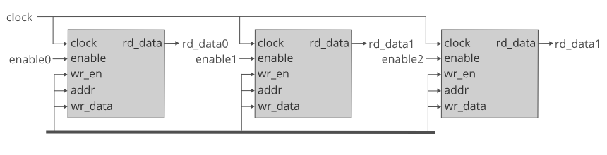
The circuit diagram shows three RAM modules connected to a bus.
We need to declare a 3-bit vector that can be used to connect to the RAM enable port. Then, we can connect different bits to each RAM block according to the value of the loop variable.
For the data output bus, we can create a 12 bit vector and connect the read data output to different 4-bit chips of the vector.
However, a more elegant solution is to use an array of three 4-bit vectors. Similarly, we can use circular variables to allocate different elements of this array as needed.
The following Verilog code snippet shows how we use the for generate statement to code the circuit.
// rd data array
wire [3:0] rd_data [2:0];

// vector for the enable signals

wire [2:0] enable;

// Genvar to use in the for loop

genvar i;


generate

  for (i=0; i<=2; i=i+1) begin

    ram ram_i (

      .clock    (clock),

      .enable   (enable[i]),

      .wr_en    (wr_en),

      .addr     (addr),

      .wr_data  (wr_data),

      .rd_data  (rd_data[i])

    );

  end

endgenerate
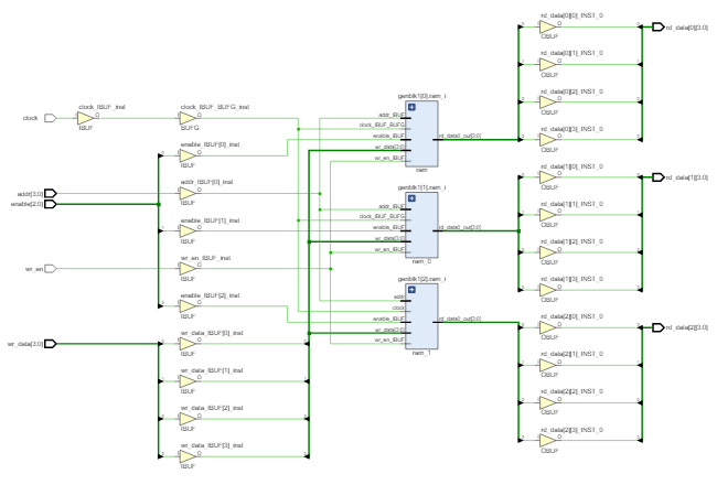
After synthesizing this code, we get the circuit shown below.
generate if statement in verilog
We use the generate if block in verilog to conditionally include verilog code blocks in our design.
When we have code that can only be used under certain conditions, we can use the generate if statement.
An example of this is when we want to include functionality specifically for testing in our design.
We can use the generate if statement to ensure that this feature is included only in the debug version and not in the production version.
The following code snippet shows the general syntax of the verilog generate if statement.
generate

  if (<condition1>) begin

    // Code to execute

  end

  else if (<condition2>) begin

    // Code to execute

  end

  else begin

    // Code to execute

  end
endgenerate
From this example, we can see that the syntax of this method is actually the same as that we see in the verilog if statement.
However, there are fundamental differences between the two methods.
When we write the generate if statement, we are actually telling the verilog compiler to create an instance of a code block according to certain conditions.
This means that only one branch is compiled, and any other branches are excluded from compilation. As a result, only one branch can be used in our design.
Conversely, when we use an IF statement, the entire if statement will be compiled and each branch of the statement can be executed.
Each time the if statement code is triggered during the simulation, the condition is evaluated to determine which branch to take.
Verilog generate if example
To better demonstrate how the verilog if statement works, let's consider a basic example.
For this example, we will write a test function that outputs a 4-bit counter value.
Since this is a test function, it needs to be activated only when using a debug version.
When building the production version of the code, we bind the counter output to the ground.
We will use parameters to determine when to build the debug version.
The following code snippet shows the implementation of this example.
// Use a parameter to control our build

parameter debug_build = 0;


// Conditionally generate a counter

generate

  if (debug_build) begin

    // Code for the counter

    always @(posedge clock, posedge reset) begin

      if (reset) begin

        count <= 4'h0;

      end

      else begin

        count <= count + 1;

      end

    end

  end

  else begin

    initial begin

      count <= 4'h0;

    end

  end

endgenerate
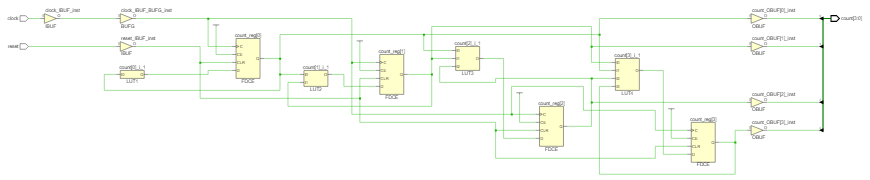
When we debug_ When the build variable is set to 1, the synthesizer will generate the circuit shown below. In this case, the synthesis tool generates a four bit counter circuit.

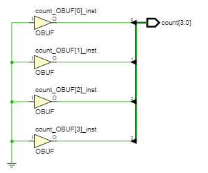
But when we debug_ When the build parameter is set to 0, the synthesis tool will generate the circuit shown below. In this case, the synthesis tool has grounded all bits of the count signal.

Verilog generate case statement
We use the generate case statement in verilog to conditionally include verilog code blocks in our design.
In essence, the generate case statement performs the same function as the generate if statement.
This means that we can also use the generate case statement when we have code that we only want to include in the design under certain conditions.
For example, we can design a test function and just want to include it in the debug version.
We can then use the generate case statement to determine which version of code to build.
The following code snippet shows the general syntax of the generate case statement in verilog.
generate

  case (<variable>)

    <value1> : begin

      // This branch executes when <variable> = <value1>

    end

    <value2> : begin

      // This branch executes when <variable> = <value2>

    end

    default : begin

    // This branch executes in all other cases

    end

  endcase

endgenerate
As you can see from this example, the syntax of this method is actually the same as that we saw in the verilog case statement.
However, there are fundamental differences between the two methods.
When we write the generate case statement, we are actually telling the verilog compiler to create an instance of the code block according to the given conditions.
This means that only one branch is compiled, and any other branches are excluded from compilation. As a result, only one branch can be used in our design.
Conversely, when we use a case statement, the entire case statement will be compiled and each branch of the statement can be executed
Each time case statement code is triggered during simulation, the condition is evaluated to determine which branch to take.
Verilog generated case example
To better illustrate how verilog generates case statements, let's look at a basic example.
Since the case statement performs the same function as the if statement, we will look at the same example again.
This means that we will write a test function that outputs a 4-bit counter.
Since this is a test function, it needs to be activated only when using a debug version.
When building the production version of the code, we bind the counter output to the ground.
We will use parameters to determine when to build the debug version.
The following verilog code shows the implementation of this example using the generate case statement.
// Use a parameter to control our build

parameter debug_build = 0;


// Conditionally generate a counter
generate

  case (debug_build)

    1 : begin

      // Code for the counter

      always @(posedge clock, posedge reset) begin

        if (reset) begin

          count <= 4'h0;

        end

        else begin

          count <= count + 1;

        end

      end

    end

    default : begin

      initial begin

        count <= 4'h0;

      end

    end

  endcase

endgenerate
When we debug_ When the build variable is set to 1, the synthesizer will generate the circuit shown below. In this case, the synthesis tool generates a four bit counter circuit.
But when we debug_ When the build parameter is set to 0, the synthesis tool will generate the circuit shown below. In this case, the synthesis tool has grounded all bits of the count signal.
practice
- What are the benefits of using parametric modules?
- We can configure the function of the module when instantiating it. This allows us to make the code easier to reuse.
- Write a generate for block and instantiate two 16 bit synchronization counters. These two counters should be used Example of parameterized module.
// Variable for the generate loop
genvar i;

// Array for the outputs

wire [15:0] count_out [1:0]

// Generate the two counters

generate

  for (i=0; i < 2, i = i+1) begin

    counter # (

      .BITS (16)

    ) count_12 (

      .clock  (clock),

      .reset  (reset),

      .count  (count_out[i])

    );

  end

endgenerate
- Write a generate for block, which instantiates an 8-bit counter or a 16 bit counter according to the value of the parameter. These two counters should use the parameterized module example earlier in this article. You can write this code using the generate case or generate if block.
// Parameter to contr, teh generate block
parameter COUNT_16 = 0;

// Using a generate case statement
generate

  case (COUNT_16)

    0 : begin

      counter # (

        .BITS (16)

      ) count_16 (

        .clock  (clock),

        .reset  (reset),

        .count  (count16_out)

      );

    end

    default : begin

      counter # (

        .BITS (8)

      ) count_8 (

        .clock  (clock),

        .reset  (reset),

        .count  (count8_out)

      );

    end

  endcase

endgenerate


// Using a generate if statement

generate

  if (COUNT_16) begin

    counter # (

      .BITS (16)

    ) count_16 (

      .clock  (clock),

      .reset  (reset),

      .count  (count16_out)

    );

  end

  else begin

    counter # (

      .BITS (8)

    ) count_8 (

      .clock  (clock),

      .reset  (reset),

      .count  (count8_out)

    );

  end

endgenerate