1, Introduction to VGA and AN430
1.VGA
VGA(Video Graphics Array) is a video transmission standard launched by IBM with PS/2 machine in 1987. At that time, it had the advantages of high resolution, fast display speed and rich colors, and was widely used in the field of color display.
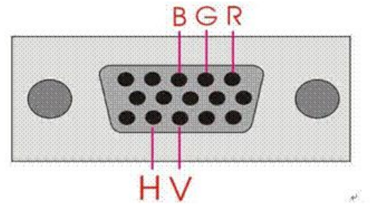
VGA interface is the interface that outputs analog signals on the graphics card, also known as D-Sub interface. VGA interface is a kind of D-port. There are 15 empty pins on it, which is divided into three rows with five in each row. VGA interface is the mainstream port in the configuration of medium and low-end computers. The physical drawing is as follows:
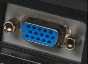
R. G, B data signals, interfaces corresponding to HS and VS control signals.
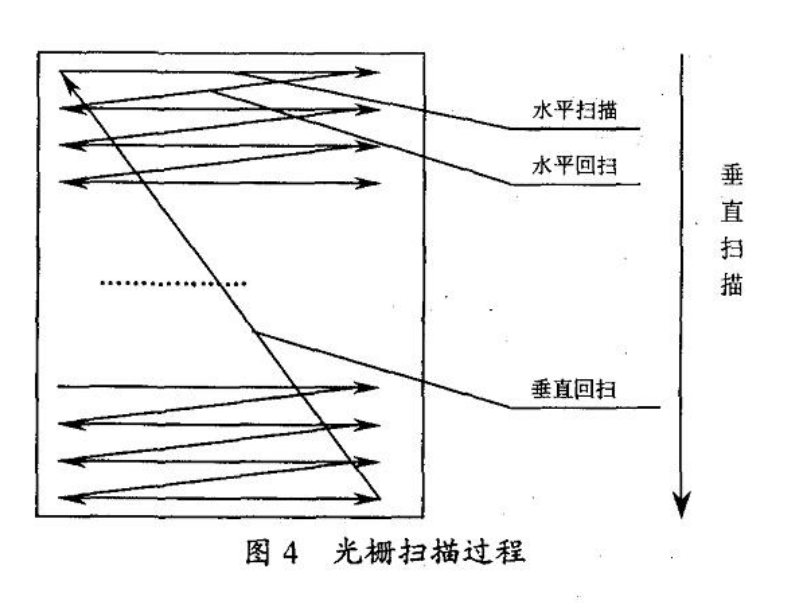
The display adopts raster scanning mode, that is, the electron beam bombarding the fluorescent screen moves regularly from left to right (controlled by horizontal synchronization signal HSYNC) and from top to bottom (controlled by vertical synchronization signal VSYNC) on the CRT screen. The electron beam adopts grating scanning mode, starting from a point in the upper left corner of the screen and scanning point by point to the right to form a horizontal line; After reaching the rightmost end, return to the left end of the next horizontal line and repeat the above process; When the electron beam completes the scanning at the lower right corner, a frame is formed. After that, the electron beam returns to the upper left starting point and starts the scanning of the next frame. This method is often called progressive scanning display.
Scanning frequency
The time to complete a line scanning is called the horizontal scanning time, and its reciprocal is called the line frequency; The time to complete a frame (whole screen) scanning is called the vertical scanning time, and its reciprocal is called the field frequency, that is, the frequency of refreshing a screen, commonly 60Hz, 75Hz and so on. The field frequency of standard VGA display is 60Hz.
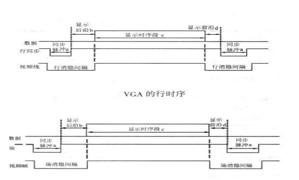
Both line timing and field timing require four parts: synchronization pulse (Sync a), Back porch b, Display interval c and Front porch d. VGA industrial standard display mode requirements: line synchronization and field synchronization are negative, that is, the synchronization pulse is required to be negative pulse.
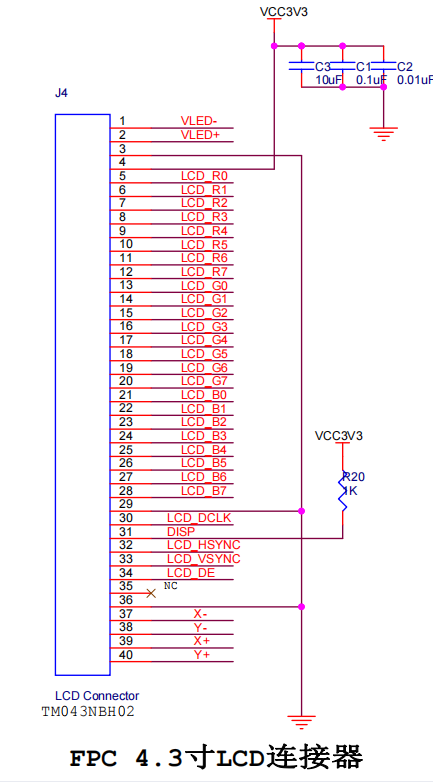
2.AN430
2, Code
1.param.v
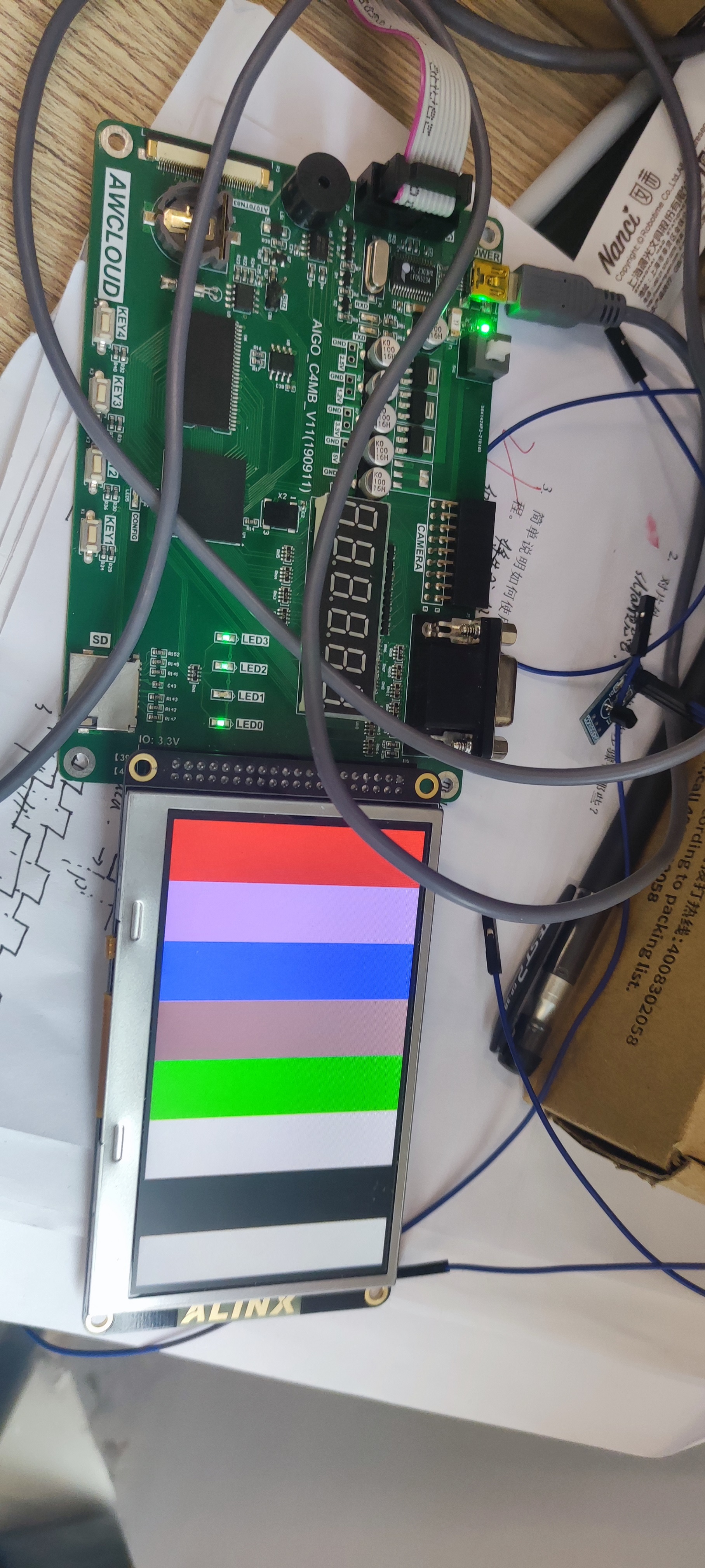
//-----------------------------------------------------------//
// Setting of horizontal scanning parameters 480*272 60Hz LCD
//-----------------------------------------------------------//

`define H_SYNC   41            	//Line sync pulse (Sync a)
`define H_BP     2             	//Show Back porch b
`define H_ACTIV  480           	//Display interval c
`define H_FP 	 2           	//Show Front porch d
`define H_TOTAL  525           	//The number of line cycles is 525 pixel cycles in total
`define H_VLD0   43				//Valid display column the first column displays data
`define H_VLD1   523			//Valid display column the last column displays data

//-----------------------------------------------------------//
// Setting of vertical scanning parameters 480*272 60Hz LCD
//-----------------------------------------------------------//

`define V_SYNC   10             //Column synchronization pulse (Sync o)
`define V_BP     2              //Show Back porch p
`define V_ACTIV  272            //Display interval q
`define V_FP     2              //Show Front porch r
`define V_TOTAL  286            //The number of column cycles is 286 rows in total
`define V_VLD0   12             //First row of valid display area
`define V_VLD1   284            //Last row of valid display area

//Color definition
`define COLOR_R 16'b11111_000000_00000
`define COLOR_G 16'b00000_111111_00000
`define COLOR_B 16'b00000_000000_11111
`define COLOR_P 16'b10110_010111_01001
`define COLOR_PU 47802
`define COLOR_PA 65402
`define COLOR_BL 16'b00000_000000_00000
`define COLOR_W  65535
2.lcd_test
module lcd_test(
    input				clk		    ,
    input				rst_n	    ,
    output      [7:0]   lcd_r       ,
    output      [7:0]   lcd_g       ,
    output      [7:0]   lcd_b       ,
    output              lcd_clk     ,
    output              lcd_vsync   ,
    output              lcd_hsync   ,
    output              lcd_de
);
    //Parameter definition

    //Intermediate signal definition

pll0	pll0_inst
(
	.areset (!rst_n     ),
	.inclk0 ( clk       ),
	.c0     ( lcd_clk   ),
	//.locked (1'b1       )
);

lcd_driver u_lcd_driver
(
    /*input                   */.clk         (lcd_clk    ),
    /*input                   */.rst_n       (rst_n      ),
    /*output      [7:0]       */.lcd_r       (lcd_r      ),
    /*output      [7:0]       */.lcd_g       (lcd_g      ),
    /*output      [7:0]       */.lcd_b       (lcd_b      ),
    /*output                  */.lcd_vsync   (lcd_vsync  ),
    /*output                  */.lcd_hsync   (lcd_hsync  ),
    /*output                  */.lcd_de      (lcd_de     )
);

endmodule
3.lcd_driver
`include "param.v"
module lcd_driver
(
    input                   clk         ,
    input                   rst_n       ,
    output      [7:0]       lcd_r       ,
    output      [7:0]       lcd_g       ,
    output      [7:0]       lcd_b       ,
    output                  lcd_clk     ,
    output                  lcd_vsync   ,
    output                  lcd_hsync   ,
    output                  lcd_de
);

    //Intermediate signal definition
    reg         [9:0]       cnt_h       ;
    wire                    add_cnt_h   ;
    wire                    end_cnt_h   ;

    reg         [9:0]       cnt_v       ;
    wire                    add_cnt_v   ;
    wire                    end_cnt_v   ;

    wire                    h_vld       ;
    wire                    v_vld       ;

    reg         [15:0]      data_rgb    ;


    //Counter
    always @(posedge clk or negedge rst_n)begin
       if(!rst_n)begin
            cnt_h <= 0;
        end
        else if(add_cnt_h)begin
                if(end_cnt_h)begin
                    cnt_h <= 0;
                end
                else begin
                    cnt_h <= cnt_h + 1;
                end
        end
       else  begin
           cnt_h <= cnt_h;
        end
    end

    assign add_cnt_h = 1'b1;
    assign end_cnt_h = add_cnt_h && cnt_h == `H_TOTAL-1;

    always @(posedge clk or negedge rst_n)begin
       if(!rst_n)begin
            cnt_v <= 0;
        end
        else if(add_cnt_v)begin
                if(end_cnt_v)begin
                    cnt_v <= 0;
                end
                else begin
                    cnt_v <= cnt_v + 1;
                end
        end
       else  begin
           cnt_v <= cnt_v;
        end
    end

    assign add_cnt_v = end_cnt_h;
    assign end_cnt_v = add_cnt_v && cnt_v == `V_TOTAL;

    assign h_vld = (cnt_h >= `H_VLD0) & (cnt_h <= `H_VLD1);
    assign v_vld = (cnt_v >= `V_VLD0) & (cnt_v <= `V_VLD1);

    assign lcd_de = h_vld & v_vld;

    //data_rgb
    always @(posedge clk or negedge rst_n)begin
        if(!rst_n)begin
            data_rgb <= 16'b0;
        end
        else if(cnt_h >= 43 && cnt_h <=103 )begin
            data_rgb <= `COLOR_R;
        end
        else if(cnt_h >= 104 && cnt_h <=164 )begin
            data_rgb <= `COLOR_PU;
        end
        else if(cnt_h >= 165 && cnt_h <=225 )begin
            data_rgb <= `COLOR_B;
        end
        else if(cnt_h >= 226 && cnt_h <=286 )begin
            data_rgb <= `COLOR_P;
        end
        else if(cnt_h >= 287 && cnt_h <=348 )begin
            data_rgb <= `COLOR_G;
        end
        else if(cnt_h >= 349 && cnt_h <=409 )begin
            data_rgb <= `COLOR_PA;
        end
		  else if(cnt_h >= 410 && cnt_h <=470 )begin
            data_rgb <= `COLOR_BL;
        end
		  else if(cnt_h >= 471  )begin
				data_rgb <= `COLOR_W;
		  end
        else begin
            data_rgb <= data_rgb;
        end
    end

    assign lcd_r = (h_vld & v_vld) ? {data_rgb[15:11],3'd0}:0;
    assign lcd_g = (h_vld & v_vld) ? {data_rgb[10:5],2'd0}:0;
    assign lcd_b = (h_vld & v_vld) ? {data_rgb[4:0],3'd0}:0;

    assign lcd_vsync = cnt_v >= `V_SYNC;
    assign lcd_hsync = cnt_h >= `H_SYNC;


endmodule
3, Result display verification