[see for the above video notes http://www.autolabor.com.cn/book/ROSTutorials/]
1, Introduction
Official link: https://www.ros.org/reps/rep-0105.html
1. Key technologies for navigation
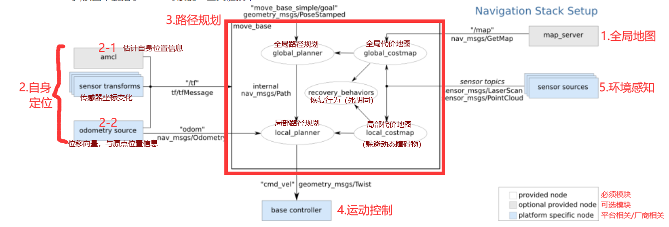
(1) global map
(global overview: positioning + path planning)
-
Slam (realizing map building and real-time positioning), also known as CML (Concurrent Mapping and Localization), real-time positioning and map building, or concurrent map building and positioning. SLAM problem can be described as: the robot starts to move from an unknown position in the unknown environment, locates itself according to the position estimation and map in the moving process, and constructs an incremental map based on its own positioning to draw a complete map of the external environment. (for example, the red alarm starts in darkness and the map appears with exploration)
The function package for saving maps in ROS is map_server
-
Sensor: to complete SLAM, the robot must have the ability to perceive the external environment, especially the ability to obtain the depth information of the surrounding environment. The realization of perception depends on sensors, such as lidar, camera and RGB-D camera
(2) Self positioning
(location in map)
- AMCL (Adaptive Monte Carlo localization) is a probabilistic positioning system for 2D mobile robot. It implements an adaptive (or KLD sampling) Monte Carlo localization method, which uses particle filter to track the robot's attitude according to the known map.
- At the beginning of navigation and during navigation, the robot needs to determine its current position, and GPS can be used outdoors. Indoor, tunnel, underground or some special areas that shield and weaken GPS signals, the front SLAM can realize its own positioning. In addition, ROS also provides a function package amcl for positioning
(3) Path planning
(Global + local path planning)
-
Global_planner
Realize the overall path planning according to the given target point and global map, use Dijkstra or A * algorithm for global path planning, and calculate the optimal route as the global route
-
Local_planner
In the actual navigation process, the robot may not run according to the given global optimal route. For example, certain obstacles may appear at any time when the robot is running The role of local planning is to use certain algorithms (dynamic window approvals) to avoid obstacles, and select the current optimal path to conform to the global optimal path as much as possible
(4) Motion control
(control speed and direction)
The navigation feature pack set assumes that it can publish geometry through the topic "cmd_vel"_ Msgs / twist type message. This message is based on the base coordinate system of the robot, which transmits motion commands. This means that a node must subscribe to the "cmd_vel" topic, convert the speed command on the topic into motor command and send it.
(5) Environmental perception
(perceive the surrounding environment)
Perceive the surrounding environment information, such as camera, lidar, encoder, The camera and lidar can be used to sense the depth information of the external environment, and the encoder can sense the speed information of the motor, so as to obtain the speed information and generate the odometer information.
In the navigation function pack, environment awareness is also an important module implementation, which provides support for other modules. Other modules such as SLAM, amcl, move_ All databases need to rely on environmental awareness.
2. Coordinate system
(1) Odometer positioning (odom)
- Odometer positioning: collect the speed information of the robot from time to time, calculate and publish the relative relationship between the robot coordinate system and the parent reference system.
- Advantages: odometer positioning information is continuous without discrete jumps.
- Disadvantages: the odometer has accumulated error, which is not conducive to long-distance or long-term positioning.
[judge the position according to the direction and how many roads you have taken]
(2) Sensor location (map)
- Sensor positioning: collect the external environment information through the sensor, calculate and release the relative relationship between the robot coordinate system and the parent reference system through matching.
- Advantages: more accurate positioning than odometer;
- Disadvantages: the sensor positioning will jump, and the positioning accuracy of the sensor will be greatly reduced in the environment with few markers.
[judge the location according to your surroundings]
(3) Coordinate system transformation
In the above two positioning implementations, the robot coordinate system generally uses the root coordinate system (base_link or base_footprint) in the robot model
During odometer positioning, the parent coordinate system is generally called odom
When positioning the sensor, the parent reference system is generally called map.
When the two are used together, map and odom are the parent of the root coordinate system of the robot model, which does not comply with the principle of "single inheritance" in coordinate transformation. Therefore, the transformation relationship is generally set to: Map - > Doom - > base_ Link or base_footprint.
3. Hardware and software requirements
(1) Hardware
Although the navigation function package is designed to be as general as possible, there are still three main hardware limitations when using it:
-
It is designed for differential driven wheeled robots. It assumes that the chassis is controlled by the ideal motion command and can achieve the expected results. The format of the command is: x velocity component, y velocity component and angular velocity (theta) component.
-
It needs to install a single line lidar on the chassis. This lidar is used to build maps and locate.
-
The navigation function package is developed for square robots, so square or circular robots will have the best performance. It can also work on robots of any shape and size, but larger robots will be difficult to pass through narrow space.
(2) Software
-
Install ROS
-
The current navigation is based on the simulation environment. First, ensure that the robot system simulation in the previous chapter can be executed normally
-
In the simulation environment, the robot can receive / CMD normally_ Vel message and release odometer message, and the release of sensor message is normal, that is, the implementation of motion control and environment perception in the navigation module is completed
2, Navigation implementation
1. Preparation
(1) Install Feature Pack
- gmapping package (for building maps)
# Sudo apt install ROS - < ROS version > - gmapping
sudo apt install ros-noetic-gmapping
- Map service package (for saving and reading maps)
# Sudo apt install ROS - < ROS version > - map server
sudo apt install ros-noetic-map-server
- navigation package (for positioning and Path Planning)
# Sudo apt install ROS - < ROS version > - Navigation
sudo apt install ros-noetic-navigation
(2) New Feature Pack
① Right click 7.19_demo01/src, create a new package catkin, name [nav_demo], and import dependencies: gmapping map_server amcl move_base
② In nav_ Create a new folder launch and map under the demo folder
2.SLAM mapping
Official link: http://wiki.ros.org/gmapping
(1) gmapping related
There are many SLAM algorithms. At present, we choose gmapping.
gmapping is one of the more common and mature SLAM algorithms in the ROS open source community. gmapping can draw a two-dimensional grid map according to mobile robot odometer data and lidar data.
The core node in the gmapping function package is slam_gmapping. In order to facilitate calling, you need to know the topics subscribed, published, services and related parameters of the node.
- Subscribed topics
tf (tf/tfMessage): used for coordinate transformation messages between radar, chassis and odometer.
scan(sensor_msgs/LaserScan): radar information required by SLAM.
- Published Topic
map_metadata(nav_msgs/MapMetaData): Map metadata, including the width, height and resolution of the map. The message will be updated regularly.
map(nav_msgs/OccupancyGrid): map grid data, which is generally displayed graphically in rviz.
~entropy(std_msgs/Float64): estimation of robot attitude distribution entropy (the greater the value, the greater the uncertainty).
- service
dynamic_map(nav_msgs/GetMap): used to obtain map data.
- Common parameters
~base_frame(string, default:"base_link"): robot base coordinate system.
~map_ "Map: default, frame: string".
~odom_frame(string, default:"odom"): odometer coordinate system.
~map_update_interval(float, default: 5.0): map update frequency. The update interval is designed according to the specified value.
~Maxrange (float, default: 80.0): the maximum available range of laser detection (beyond this threshold, it is truncated).
Maximum range of laser detection.
- Coordinate transformation required
Radar coordinate system → base coordinate system: generally by robot_state_publisher or static_transform_publisher posted.
Base coordinate system → odometer coordinate system: generally released by odometer node.
- Published coordinate transformations
Map coordinate system → odometer coordinate system: transformation from map to odometer coordinate system.
(2) Drawing code
In nav_ Create a new T1 in Demo01 / Launch folder_ slam. launch
<launch>
    <!-- Set to true Indicates that the current environment is a simulation environment -->
    <param name="use_sim_time" value="true" />
    <!-- gamping node -->
    <node pkg="gmapping" type="slam_gmapping" name="slam_gmapping" output="screen">
        <!-- Set radar topic -->
        <remap from="scan" to="scan" />

        <!-- Key parameters: coordinate system -->
        <param name="base_frame" value="base_footprint" /> <!--Chassis coordinate system-->
        <param name="odom_frame" value="odom" /> <!--Odometer coordinate system-->
        <param name="map_frame" value="map" /> <!--Map coordinate system-->

        <param name="map_update_interval" value="5.0" />
        <param name="maxUrange" value="16.0" />
        <param name="sigma" value="0.05" />
        <param name="kernelSize" value="1" />
        <param name="lstep" value="0.05" />
        <param name="astep" value="0.05" />
        <param name="iterations" value="5" />
        <param name="lsigma" value="0.075" />
        <param name="ogain" value="3.0" />
        <param name="lskip" value="0" />
        <param name="srr" value="0.1" />
        <param name="srt" value="0.2" />
        <param name="str" value="0.1" />
        <param name="stt" value="0.2" />
        <param name="linearUpdate" value="1.0" />
        <param name="angularUpdate" value="0.5" />
        <param name="temporalUpdate" value="3.0" />
        <param name="resampleThreshold" value="0.5" />
        <param name="particles" value="30" />
        <param name="xmin" value="-50.0" />
        <param name="ymin" value="-50.0" />
        <param name="xmax" value="50.0" />
        <param name="ymax" value="50.0" />
        <param name="delta" value="0.05" />
        <param name="llsamplerange" value="0.01" />
        <param name="llsamplestep" value="0.01" />
        <param name="lasamplerange" value="0.005" />
        <param name="lasamplestep" value="0.005" />
    </node>

    <node pkg="joint_state_publisher" name="joint_state_publisher" type="joint_state_publisher" />
    <node pkg="robot_state_publisher" name="robot_state_publisher" type="robot_state_publisher" />

    <!-- <node pkg="rviz" type="rviz" name="rviz" /> -->
    <!-- Use previously saved rviz to configure-->
    <node pkg="rviz" type="rviz" name="rviz" args="-d $(find urdf_gazebo)/config/t7_car.rviz" />

</launch>
(3) Start
① Run relevant startup commands
ctrl+shift+b   # compile

# Terminal 1
roscore

# Terminal 2 (gazebo before startup)
roslaunch urdf_gazebo t7_gazebo.launch

# Terminal 3 (start the new map drawing launch)
roslaunch nav_demo t1_slam.launch

# External new terminal 1 (start keyboard control)
rosrun teleop_twist_keyboard teleop_twist_keyboard.py
② Add → map → Topic: / map in Rviz
You can see a map in rviz. Control the trolley movement to further draw the map
③ Open TF → Frames → check map, odom and base_footprint
When checked, the map and odm coordinates of the starting point, base, will be displayed_ Footprint can display the distance relationship between the current position and the origin. Other options can be adjusted as needed

3. Map saving and reading
Official link: http://wiki.ros.org/map_server
map_ The server function pack provides two nodes: map_ Savers and maps_ Server, the former is used to save the grid map to the disk, and the latter reads the grid map on the disk and provides it as a service.
(1)map_sarver correlation
- Subscribed topics
map(nav_msgs/OccupancyGrid): subscribe to this topic to generate map files.
(2)map_server related
- Published Topic
map_metadata (nav_msgs / MapMetaData): publish map metadata.
Map (nav_msgs / OccupancyGrid): map data.
- service
static_map (nav_msgs / GetMap): get the map through this service.
- parameter
〜frame_id (string, default: "map"): map coordinate system.
(3) Map saving
① New T2 for map saving_ map_ save. Launch file
<launch>
    <!-- nav Folders may not be created -->
    <arg name="filename" value="$(find nav_demo)/map/nav" />
    <node name="map_save" pkg="map_server" type="map_saver" args="-f $(arg filename)" />
</launch>
② After drawing, run t2_map_save.launch
# New terminal
roslaunch nav_demo t2_map_save.launch
③ Check
In nav_ In the demo / map directory, you will see that two map files have been generated
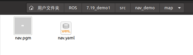
- xxx.pgm is essentially a picture
Directly use the picture viewer to open it.

- xxx.yaml saves the metadata information of the map
It is used to describe pictures. The content format is as follows:
# Picture path can be absolute path or relative path
image: /home/netceor_ros/ROS/7.19_demo1/src/nav_demo/map/nav.pgm
# Resolution (unit: m / pixel), map scale unit
resolution: 0.050000
# Map pose, relative to rviz original point pose. (x, y, yaw) yaw is counterclockwise rotation (yaw = 0 means no rotation)
origin: [-50.000000, -50.000000, 0.000000]
# Negation: should the semantics of white / black free / occupied be reversed
negate: 0
# Occupancy threshold: pixels with occupancy probability greater than this threshold are considered to be fully occupied
occupied_thresh: 0.65
# Idle threshold: pixels with occupancy less than this threshold are considered completely idle
free_thresh: 0.196
- map_ Obstacle calculation rules in server
a. The value of each pixel in the map is between [0255], white is 255, black is 0, and the value is set to x;
b.map_ The server will take the pixel value as the basis for judging whether it is an obstacle. First, calculate the scale: p = (255 - x) / 255.0, white is 0, black is 1 (if negative is true, p = x / 255.0);
c. Judge whether it is an obstacle according to the proportion calculated in step 2, if P > occupied_ Thresh, then it is regarded as an obstacle if P < free_ Thresh is then regarded as nothing.
(4) Map reading
① New T3 for map reading_ map_ load. Launch file
<launch>
    <!-- Set the profile for the map -->
    <arg name="map" default="nav.yaml" />
    <!-- Run the map server and load the set map-->
    <node name="map_server" pkg="map_server" type="map_server" args="$(find nav_demo)/map/$(arg map)" />
</launch>
② Start command
ctrl+shift+b  # compile

# After the integration terminal 1 runs, the map information is released
roslaunch nav_demo t3_map_load.launch

# External new terminal 2, start a rviz
rviz

# External new Terminal 3, check the topic. If there is a map related, it indicates that it has been successfully published
# rostopic list
③ In Rviz → Add → map → Topic: / Map
[there was no map topic when I started it for the first time. It will be useful after restarting vscode]

Robot model building reference:
Introduction to ROS (V) -- simulation robot I (URDF+Rviz)
Introduction to ROS (VI) -- simulation robot II (Xacro+Rviz+Arbotix trolley movement)
Introduction to ROS (VII) -- simulation robot III (Gazebo+Xacro)