Previous reference Introduction to ROS (V) -- simulation robot I (URDF+Rviz)
1, Introduction
1.Xacro action
Xacro is the abbreviation of XML Macros. Xacro is an XML macro language, which is programmable XML.
For a robot, we often have multiple similar components, such as the left and right wheels of the car. Directly writing URDF files will lead to duplication of code. Therefore, we need Xacro to play the role of function encapsulation. In Xacro, some parameters can be set as quantitative and variable. Variables are passed in during creation to realize batch generation of similar components.
It can also realize variable calculation and solution, and avoid human labor in some operations.
2. Objectives
1.Create a for the base and wheels xacro file
2.Write camera and radar xacro file
3.Write a combination file to combine chassis, camera and radar
4.adopt launch File startup Rviz And display the model
3.Xacro syntax
(1) Attributes
- Define properties
That is to define some constants and values, such as trolley height and ground distance, which are fixed in this practice. For example, to define PI=3.1415927
<xacro:property name="PI" value="3.1415927" />
- Property call
${Attribute name}- Arithmetic operation
${mathematical expression }(2) macro
- Macro definition
That is, the functions in the algorithm can encapsulate the same structure and attributes
<!-- Multiple parameters are separated by spaces -->
<xacro:macro name="Macro name" params="Parameter 1 Parameter 2 ..">
    .....
</xacro:macro>- Macro call
Call the created macro and pass in a batch of parameters, which are consistent with the parameters defined in the macro.
<xacro:Macro name parameter 1="xxx" Parameter 2="yyy" ../>
(3) Calculation example
Implement macro definition and macro call of 1 + 6 = 7
<robot name="t" xmlns:xacro="http://wiki.ros.org/xacro">
    <!-- 1.Macro definition -->
    <xacro:macro name="getsum" params="num1 num2">
        <result value="${num1+num2}"/>
    </xacro:macro>
    <!-- 2.Macro call -->
    <xacro:getsum num1="1" num2="6"/>
</robot>
(4) Combination example
After the xacro file of individual components is written, we will want to combine more components together and splice them into a complete model. We need to generate a new xacro file for combination and call the file directly when running launch.
<robot name="xxx" xmlns:xacro="http://wiki.ros.org/xacro">
      <xacro:include filename="File 1.xacro" />
      <xacro:include filename="Document 2.xacro" />
      <xacro:include filename="Document 3.xacro" />
      ....
</robot>
2, Create car body, camera and radar respectively
1. Create base and wheel (body)
In the xacro folder generated in the previous article, we created an xacro file [t1_car.xacro] representing the car body
<!--
    1.utilize xacro:property To encapsulate constants
    2.Use macro to construct similar wheels (left and right wheels are similar, front and rear wheels are similar)
-->
<!-- Root label, must declare xmlns:xacro -->
<robot name="my_base" xmlns:xacro="http://www.ros.org/wiki/xacro">
    <!-- Encapsulating variables and constants -->
    <xacro:property name="PI" value="3.141" />
    <!-- macro:Black settings -->
    <material name="black">
        <color rgba="0.0 0.0 0.0 1.0" />
    </material>
    <!-- Encapsulated chassis properties -->
    <xacro:property name="base_footprint_radius" value="0.001" /> <!-- base_footprint radius  -->
    <xacro:property name="base_link_radius" value="0.1" /> <!-- base_link radius -->
    <xacro:property name="base_link_length" value="0.08" /> <!-- base_link long -->
    <xacro:property name="earth_space" value="0.015" /> <!-- Ground clearance -->

    <!-- There is only one chassis, which is written directly -->
    <link name="base_footprint">
        <visual>
            <geometry>
                <sphere radius="${base_footprint_radius}" />
            </geometry>
        </visual>
    </link>

    <link name="base_link">
        <visual>
            <geometry>
                <cylinder radius="${base_link_radius}" length="${base_link_length}" />
            </geometry>
            <origin xyz="0 0 0" rpy="0 0 0" />
            <material name="yellow">
                <color rgba="0.5 0.3 0.0 0.5" />
            </material>
        </visual>
    </link>

    <joint name="base_link2base_footprint" type="fixed">
        <parent link="base_footprint" />
        <child link="base_link" />
        <origin xyz="0 0 ${earth_space + base_link_length / 2 }" />
    </joint>

    <!-- Drive wheel -->
    <!-- Drive wheel attribute encapsulation -->
    <xacro:property name="wheel_radius" value="0.0325" /> <!-- radius -->
    <xacro:property name="wheel_length" value="0.015" /> <!-- width -->
    <!-- Macro implementation of driving wheel -->
    <xacro:macro name="add_wheels" params="name flag">
        <link name="${name}_wheel">
            <visual>
                <geometry>
                    <cylinder radius="${wheel_radius}" length="${wheel_length}" />
                </geometry>
                <origin xyz="0.0 0.0 0.0" rpy="${PI / 2} 0.0 0.0" />
                <material name="black" />
            </visual>
        </link>

        <joint name="${name}_wheel2base_link" type="continuous">
            <parent link="base_link" />
            <child link="${name}_wheel" />
            <origin xyz="0 ${flag * base_link_radius} ${-(earth_space + base_link_length / 2 - wheel_radius) }" />
            <axis xyz="0 1 0" />
        </joint>
    </xacro:macro>
    <!-- Macro call, add left and right wheels -->
    <xacro:add_wheels name="left" flag="1" />
    <xacro:add_wheels name="right" flag="-1" />

    <!-- Supporting wheel -->
    <!-- Support wheel properties -->
    <xacro:property name="support_wheel_radius" value="0.0075" /> <!-- Radius of supporting wheel -->
    <!-- Support wheel macro -->
    <xacro:macro name="add_support_wheel" params="name flag">
        <link name="${name}_wheel">
            <visual>
                <geometry>
                    <sphere radius="${support_wheel_radius}" />
                </geometry>
                <origin xyz="0 0 0" rpy="0 0 0" />
                <material name="black" />
            </visual>
        </link>
        <!-- Joint macro of supporting wheel and chassis -->
        <joint name="${name}_wheel2base_link" type="continuous">
            <parent link="base_link" />
            <child link="${name}_wheel" />
            <origin xyz="${flag * (base_link_radius - support_wheel_radius)} 0 ${-(base_link_length / 2 + earth_space / 2)}" />
            <axis xyz="1 1 1" />
        </joint>
    </xacro:macro>
    <!-- Macro call to add front and rear support wheels -->
    <xacro:add_support_wheel name="front" flag="1" />
    <xacro:add_support_wheel name="back" flag="-1" />
</robot>
2. Create a camera
In the xacro folder generated in the previous article, we created an xacro file representing the camera [t2_camera.xacro]
<!-- Camera related xacro file -->
<robot name="my_camera" xmlns:xacro="http://wiki.ros.org/xacro">
    <!-- Camera properties -->
    <xacro:property name="camera_length" value="0.01" /> <!-- Camera length(x) -->
    <xacro:property name="camera_width" value="0.025" /> <!-- Camera width(y) -->
    <xacro:property name="camera_height" value="0.025" /> <!-- Camera height(z) -->
    <xacro:property name="camera_x" value="0.08" /> <!-- Camera mounted x coordinate -->
    <xacro:property name="camera_y" value="0.0" /> <!-- Camera mounted y coordinate -->
    <xacro:property name="camera_z" value="${base_link_length / 2 + camera_height / 2}" /> <!-- Camera mounted z coordinate:Chassis height / 2 + Camera height / 2  -->

    <!-- Camera joints and link -->
    <link name="camera">
        <visual>
            <geometry>
                <box size="${camera_length} ${camera_width} ${camera_height}" />
            </geometry>
            <origin xyz="0.0 0.0 0.0" rpy="0.0 0.0 0.0" />
            <material name="black" />
        </visual>
    </link>

    <joint name="camera2base_link" type="fixed">
        <parent link="base_link" />
        <child link="camera" />
        <origin xyz="${camera_x} ${camera_y} ${camera_z}" />
    </joint>
</robot>
3. Create a camera
In the xacro folder generated in the previous article, we created an xacro file representing radar [t3_laser.xacro]
<!-- Camera related xacro file -->
<robot name="my_camera" xmlns:xacro="http://wiki.ros.org/xacro">
    <!-- Camera properties -->
    <xacro:property name="camera_length" value="0.01" /> <!-- Camera length(x) -->
    <xacro:property name="camera_width" value="0.025" /> <!-- Camera width(y) -->
    <xacro:property name="camera_height" value="0.025" /> <!-- Camera height(z) -->
    <xacro:property name="camera_x" value="0.08" /> <!-- Camera mounted x coordinate -->
    <xacro:property name="camera_y" value="0.0" /> <!-- Camera mounted y coordinate -->
    <xacro:property name="camera_z" value="${base_link_length / 2 + camera_height / 2}" /> <!-- Camera mounted z coordinate:Chassis height / 2 + Camera height / 2  -->

    <!-- Camera joints and link -->
    <link name="camera">
        <visual>
            <geometry>
                <box size="${camera_length} ${camera_width} ${camera_height}" />
            </geometry>
            <origin xyz="0.0 0.0 0.0" rpy="0.0 0.0 0.0" />
            <material name="black" />
        </visual>
    </link>

    <joint name="camera2base_link" type="fixed">
        <parent link="base_link" />
        <child link="camera" />
        <origin xyz="${camera_x} ${camera_y} ${camera_z}" />
    </joint>
</robot>
3, Component combination
Method 1 (not recommended): combine after converting to urdf
Open the inheritance terminal under xacro folder and run.
# rosrun xacro xacro xxx.xacro > xxx.urdf
rosrun xacro xacro t1_car.xacro > t1_xacro_car.urdf
At this point, xacro is converted to urdf file and then called in launch. Call method can refer to Introduction to ROS (V) -- simulation robot I (URDF+Rviz)
Method 2 (recommended): create a new xacro combination file
After writing the xacro file of individual components, we will want to combine more components together and splice them into a complete model. We need to generate a new xacro file for combination. When running launch, we can call the file directly to display all components together.
xacro to be combined:
- t1_car.xacro [body + wheel]
- t2_camera.xacro [camera]
- t3_laser.xacro [radar]
Create a new t4_123combine.xacro file, combining various components
<!-- Combined trolley, camera and radar -->
<robot name="my_car_camera" xmlns:xacro="http://wiki.ros.org/xacro">
    <xacro:include filename="t1_car.xacro" />
    <xacro:include filename="t2_camera.xacro" />
    <xacro:include filename="t3_laser.xacro" />
</robot>
4, launch calls xacro and runs rviz
(1) Edit launch file
Create a new launch file under the Launch folder [t4_xacro.launch]
<launch>
    <!-- take xacro The file content is set into the parameter server -->
    <!-- urdf Call mode -->
    <!-- <param name="robot_description" textfile="$(find urdf_rviz)/urdf/urdf/t1_car.urdf" /> -->
    <!-- xacro Call mode -->
    <param name="robot_description" command="$(find xacro)/xacro $(find urdf_rviz)/urdf/xacro/t4_123combine.xacro" />

    <!-- start-up rivz -->
    <node pkg="rviz" type="rviz" name="rviz" args="-d $(find urdf_rviz)/config/t1_car.rviz" />
    <!-- <node pkg="rviz" type="rviz" name="rviz" /> -->

    <!-- Start the robot status and joint status publishing node -->
    <node pkg="joint_state_publisher" type="joint_state_publisher" name="joint_state_publisher" output="screen" />
    <node pkg="robot_state_publisher" type="robot_state_publisher" name="robot_state_publisher" output="screen" />

    <!-- Start the graphical control joint motion node -->
    <node pkg="joint_state_publisher_gui" type="joint_state_publisher_gui" name="joint_state_publisher_gui" output="screen" />
</launch>
(2) Run the launch file
① ctrl+shift+b compile
② Open new terminal 1
roscore
③ Open new terminal 2
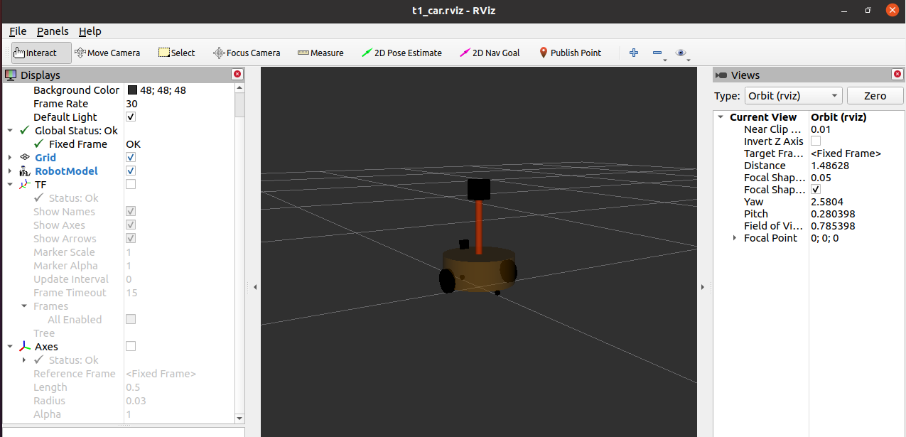
roslaunch urdf_rviz t4_xacro.launch
Normal display
[see for the above video notes http://www.autolabor.com.cn/book/ROSTutorials/]