Previously, I wrote two articles on shader to realize RGBA to YUV:
Some links about YUV images are also posted here for unfamiliar students to consult.
Shader realizes RGBA to I420
Images in I420 format are common in video decoding. As mentioned in the previous article, shaders are generally used to convert RGBA to YUV in projects. In this way, when glReadPixels are used to read images, the amount of transmitted data can be effectively reduced, the performance can be improved, and the compatibility is good.
Therefore, when reading the OpenGL rendering results, first use the Shader to convert RGBA to YUV, and then read it. This method is very efficient and convenient.
For example, the amount of data in YUYV format relative to RGBA can be reduced to 50%, while that in NV21 or I420 format can be reduced to 37.5%.
Of course, there are many ways to read OpenGL rendering results, depending on specific requirements and usage scenarios. For details, please refer to the article: Which is better for OpenGL rendered image reading?
Students familiar with the I420 format should know very well that the I420 has three planes. One plane stores Y components and the other two planes store UV components respectively.
The width and height of Y plane are the width and height of the image, and the width and height of U plane and V plane are half of the width and height of the original image respectively, so the memory occupied by I420 image is width height + width height / 42 = width height * 1.5.
Note this size. The texture used in the subsequent application for the color buffer is also this size, which is used to save the generated I420 image (it is easy to understand in this way).
Set the size of the render buffer texture according to this size:
glTexImage2D(GL_TEXTURE_2D, 0, GL_RGBA, m_RenderImage.width / 4, m_RenderImage.height * 1.5, 0, GL_RGBA, GL_UNSIGNED_BYTE, nullptr);
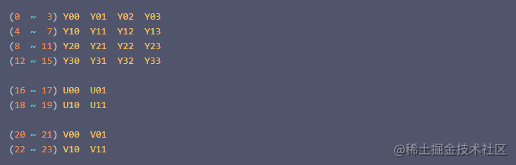
The texture used to save the generated I420 image can be simply abstracted into the following structure (in fact, the data in the texture is not arranged in this way):
Why is the width width/4? Because we use RGBA texture, a pixel occupies 4 bytes, and we only need one byte for each Y.
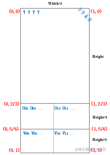
It can be seen from the texture coordinates on the figure that in the range of texture coordinates y < (2 / 3), it is necessary to complete one sampling of the whole texture to generate the image of Y plane;
When the texture coordinates are in the range of Y > (2 / 3) and Y < (5 / 6), the whole texture needs to be sampled again to generate the image of U plane;
Similarly, when the texture coordinate Y > (5 / 6) range, the whole texture is sampled again to generate the image of V plane
The most important thing is to set the viewport correctly: glViewport(0, 0, width / 4, height * 1.5).
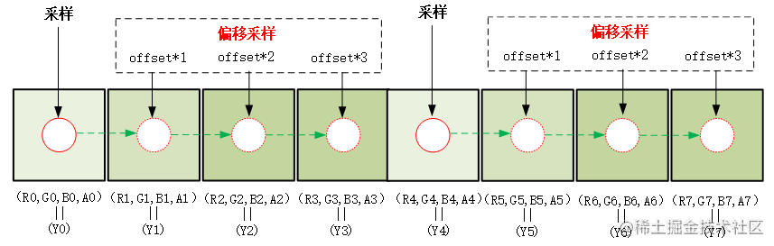
Since the viewport width is set to 1 / 4 of the original, it can be simply considered (actually more complex) to sample every 4 pixels relative to the original image. Since we need to sample every pixel in the image of Y plane, we also need to do 3 offset samples.
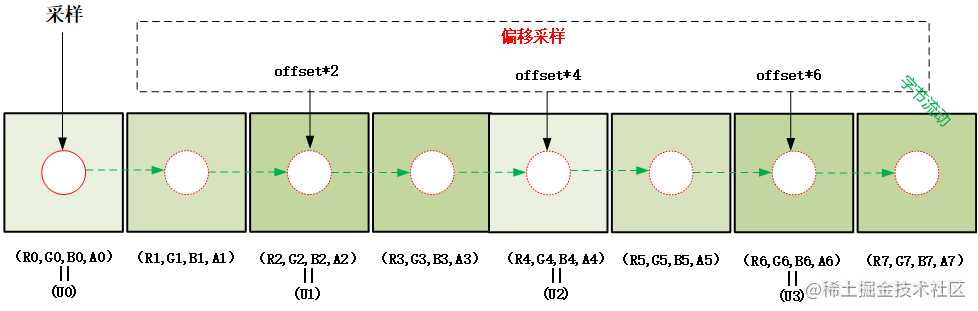
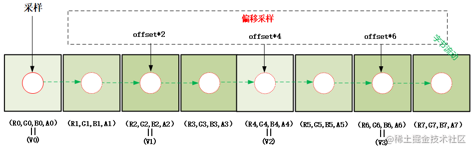
Similarly, the images of U-plane and v-plane also need to be offset sampled three times. The difference is that 2 pixels need to be offset each time.
offset needs to be set to the normalized value of one pixel: 1.0/width. According to the schematic diagram, the sampling process is simplified to 4 pixels for ease of understanding.
In the range of texture coordinate y < (2 / 3), four RGBA pixels (R,G,B,A) are sampled at one time (plus three offset samples) to generate one (Y0,Y1,Y2,Y3), and the buffer of width*height is filled at the end of sampling in the whole range;
When the texture coordinates Y > (2 / 3) and Y < (5 / 6) range, 8 RGBA pixels (R,G,B,A) are sampled (plus three offset samples) to generate (U0,U1,U2,U3). Also, because the width and height of the U plane buffer are 1 / 2 of the original image, the sampling of the U plane in the vertical and horizontal directions is interlaced, and the buffer with the size of width*height/4 is filled at the end of the sampling in the whole range.
When the texture coordinate Y > (5 / 6) range, 8 RGBA pixels (R,G,B,A) are sampled (plus three offset samples) to generate (V0,V1,V2,V3). Similarly, because the width and height of the V plane buffer are 1 / 2 of the original image, the vertical and horizontal directions are interlaced sampling, and the buffer of width*height/4 is filled at the end of the whole range sampling.
Finally, we use glReadPixels to read the generated I420 image (note width and height):
glReadPixels(0, 0, width / 4, height * 1.5, GL_RGBA, GL_UNSIGNED_BYTE, pBuffer);
code implementation

In the previous section, we discussed in detail the principle of Shader's implementation of RGBA to I420. Next, we will directly post several key implementation codes.
When creating an FBO, you need to pay attention to the size of the texture as a color buffer (width / 4, height * 1.5), which has been explained in detail above.
bool RGB2I420Sample::CreateFrameBufferObj()
{
	// Create and initialize FBO textures
	glGenTextures(1, &m_FboTextureId);
	glBindTexture(GL_TEXTURE_2D, m_FboTextureId);
	glTexParameterf(GL_TEXTURE_2D, GL_TEXTURE_WRAP_S, GL_CLAMP_TO_EDGE);
	glTexParameterf(GL_TEXTURE_2D, GL_TEXTURE_WRAP_T, GL_CLAMP_TO_EDGE);
	glTexParameteri(GL_TEXTURE_2D, GL_TEXTURE_MIN_FILTER, GL_LINEAR);
	glTexParameteri(GL_TEXTURE_2D, GL_TEXTURE_MAG_FILTER, GL_LINEAR);
	glBindTexture(GL_TEXTURE_2D, GL_NONE);

	// Create and initialize FBO
	glGenFramebuffers(1, &m_FboId);
	glBindFramebuffer(GL_FRAMEBUFFER, m_FboId);
	glBindTexture(GL_TEXTURE_2D, m_FboTextureId);
	glFramebufferTexture2D(GL_FRAMEBUFFER, GL_COLOR_ATTACHMENT0, GL_TEXTURE_2D, m_FboTextureId, 0);
	//When creating an FBO, you need to pay attention to the size of the texture as a color buffer (width / 4, height * 1.5)
	glTexImage2D(GL_TEXTURE_2D, 0, GL_RGBA, m_RenderImage.width / 4, m_RenderImage.height * 1.5, 0, GL_RGBA, GL_UNSIGNED_BYTE, nullptr);
	if (glCheckFramebufferStatus(GL_FRAMEBUFFER)!= GL_FRAMEBUFFER_COMPLETE) {
		LOGCATE("RGB2I420Sample::CreateFrameBufferObj glCheckFramebufferStatus status != GL_FRAMEBUFFER_COMPLETE");
		return false;
	}
	glBindTexture(GL_TEXTURE_2D, GL_NONE);
	glBindFramebuffer(GL_FRAMEBUFFER, GL_NONE);
	return true;

}
Complete shader script for converting RGBA to I420:
#version 300 es
precision mediump float;
in vec2 v_texCoord;
layout(location = 0) out vec4 outColor;
uniform sampler2D s_TextureMap;
uniform float u_Offset;//Offset 1.0/width
uniform vec2 u_ImgSize;//Image size
//Y =  0.299R + 0.587G + 0.114B
//U = -0.147R - 0.289G + 0.436B
//V =  0.615R - 0.515G - 0.100B
const vec3 COEF_Y = vec3( 0.299,  0.587,  0.114);
const vec3 COEF_U = vec3(-0.147, -0.289,  0.436);
const vec3 COEF_V = vec3( 0.615, -0.515, -0.100);
const float U_DIVIDE_LINE = 2.0 / 3.0;
const float V_DIVIDE_LINE = 5.0 / 6.0;
void main()
{
    vec2 texelOffset = vec2(u_Offset, 0.0);
    if(v_texCoord.y <= U_DIVIDE_LINE) {
        //In the range of texture coordinate y < (2 / 3), the whole texture needs to be sampled once,
        //Four RGBA pixels (R,G,B,A) are sampled at one time (plus three offset samples) to generate one (Y0,Y1,Y2,Y3), and the buffer of width*height is filled at the end of sampling in the whole range;

        vec2 texCoord = vec2(v_texCoord.x, v_texCoord.y * 3.0 / 2.0);
        vec4 color0 = texture(s_TextureMap, texCoord);
        vec4 color1 = texture(s_TextureMap, texCoord + texelOffset);
        vec4 color2 = texture(s_TextureMap, texCoord + texelOffset * 2.0);
        vec4 color3 = texture(s_TextureMap, texCoord + texelOffset * 3.0);

        float y0 = dot(color0.rgb, COEF_Y);
        float y1 = dot(color1.rgb, COEF_Y);
        float y2 = dot(color2.rgb, COEF_Y);
        float y3 = dot(color3.rgb, COEF_Y);
        outColor = vec4(y0, y1, y2, y3);
    }
    else if(v_texCoord.y <= V_DIVIDE_LINE){

		//When the texture coordinate Y > (2 / 3) and Y < (5 / 6) range, 8 RGBA pixels (R,G,B,A) are generated (U0,U1,U2,U3) for one sampling (plus three offset sampling),
		//In addition, because the width and height of the U-plane buffer are 1 / 2 of the original figure, the sampling of the U-plane in the vertical and horizontal directions is carried out every other line, and the buffer with the size of width*height/4 is filled at the end of the sampling in the whole range.

        float offsetY = 1.0 / 3.0 / u_ImgSize.y;
        vec2 texCoord;
        if(v_texCoord.x <= 0.5) {
            texCoord = vec2(v_texCoord.x * 2.0, (v_texCoord.y - U_DIVIDE_LINE) * 2.0 * 3.0);
        }
        else {
            texCoord = vec2((v_texCoord.x - 0.5) * 2.0, ((v_texCoord.y - U_DIVIDE_LINE) * 2.0 + offsetY) * 3.0);
        }

        vec4 color0 = texture(s_TextureMap, texCoord);
        vec4 color1 = texture(s_TextureMap, texCoord + texelOffset * 2.0);
        vec4 color2 = texture(s_TextureMap, texCoord + texelOffset * 4.0);
        vec4 color3 = texture(s_TextureMap, texCoord + texelOffset * 6.0);

        float u0 = dot(color0.rgb, COEF_U) + 0.5;
        float u1 = dot(color1.rgb, COEF_U) + 0.5;
        float u2 = dot(color2.rgb, COEF_U) + 0.5;
        float u3 = dot(color3.rgb, COEF_U) + 0.5;
        outColor = vec4(u0, u1, u2, u3);
    }
    else {
		//When the texture coordinate Y > (5 / 6) range, 8 RGBA pixels (R,G,B,A) are generated by one sampling (plus three offset sampling) (V0,V1,V2,V3),
		//Similarly, because the width and height of the V plane buffer are 1 / 2 of the original figure, the vertical and horizontal directions are interlaced sampling, and the buffer with the size of width*height/4 is filled at the end of the sampling in the whole range.

        float offsetY = 1.0 / 3.0 / u_ImgSize.y;
        vec2 texCoord;
        if(v_texCoord.x <= 0.5) {
            texCoord = vec2(v_texCoord.x * 2.0, (v_texCoord.y - V_DIVIDE_LINE) * 2.0 * 3.0);
        }
        else {
            texCoord = vec2((v_texCoord.x - 0.5) * 2.0, ((v_texCoord.y - V_DIVIDE_LINE) * 2.0 + offsetY) * 3.0);
        }

        vec4 color0 = texture(s_TextureMap, texCoord);
        vec4 color1 = texture(s_TextureMap, texCoord + texelOffset * 2.0);
        vec4 color2 = texture(s_TextureMap, texCoord + texelOffset * 4.0);
        vec4 color3 = texture(s_TextureMap, texCoord + texelOffset * 6.0);

        float v0 = dot(color0.rgb, COEF_V) + 0.5;
        float v1 = dot(color1.rgb, COEF_V) + 0.5;
        float v2 = dot(color2.rgb, COEF_V) + 0.5;
        float v3 = dot(color3.rgb, COEF_V) + 0.5;
        outColor = vec4(v0, v1, v2, v3);
    }
}
Off screen rendering and I420 image reading:
void RGB2I420Sample::Draw(int screenW, int screenH)
{
	// offscreen rendering
	glBindFramebuffer(GL_FRAMEBUFFER, m_FboId);
    // Rendered as I420, the width pixel becomes 1 / 4 of the width and the height is height * 1.5
    glViewport(0, 0, m_RenderImage.width / 4, m_RenderImage.height * 1.5);
	glUseProgram(m_FboProgramObj);
	glBindVertexArray(m_VaoIds[1]);
	glActiveTexture(GL_TEXTURE0);
	glBindTexture(GL_TEXTURE_2D, m_ImageTextureId);
	glUniform1i(m_FboSamplerLoc, 0);

	float texelOffset = (float) (1.f / (float) m_RenderImage.width);
	GLUtils::setFloat(m_FboProgramObj, "u_Offset", texelOffset);
    GLUtils::setVec2(m_FboProgramObj, "u_ImgSize", m_RenderImage.width, m_RenderImage.height);

	glDrawElements(GL_TRIANGLES, 6, GL_UNSIGNED_SHORT, (const void *)0);
	glBindVertexArray(0);
	glBindTexture(GL_TEXTURE_2D, 0);

	//I420 buffer = width * height * 1.5;
	uint8_t *pBuffer = new uint8_t[m_RenderImage.width * m_RenderImage.height * 3 / 2];

	NativeImage nativeImage = m_RenderImage;
	nativeImage.format = IMAGE_FORMAT_I420;
	nativeImage.ppPlane[0] = pBuffer;
	nativeImage.ppPlane[1] = pBuffer + m_RenderImage.width * m_RenderImage.height;
    nativeImage.ppPlane[2] = nativeImage.ppPlane[1] + m_RenderImage.width * m_RenderImage.height / 4;

	//Use glReadPixels to read the generated I420 image (note width and height)
	glReadPixels(0, 0, nativeImage.width / 4, nativeImage.height * 1.5, GL_RGBA, GL_UNSIGNED_BYTE, pBuffer);


	//Save YUV pictures in I420 format
	std::string path(DEFAULT_OGL_ASSETS_DIR);
	NativeImageUtil::DumpNativeImage(&nativeImage, path.c_str(), "RGB2I420");
	delete []pBuffer;

	glBindFramebuffer(GL_FRAMEBUFFER, 0);

}
Question: why is the efficiency of converting RGBA to I420 using shader not as high as that of converting NV21?
It's not easy to code. Give me a favor! See the project for the complete implementation code: https://github.com/githubhaohao/NDK_OpenGLES_3_0 , select RGB to I420 demo in the upper right corner.