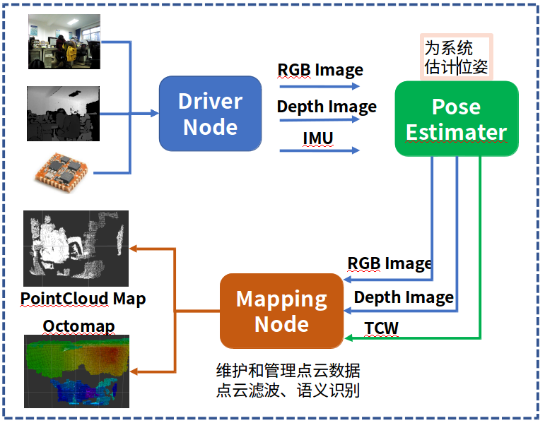
This blog continues with the content in the previous blog. We have completed the modification of pose estimator in the front, that is to say, the ROS node provided by ORB-SLAM is used to realize online operation. Review our goal is to divide the mapping system into three nodes. The driving node is mainly responsible for receiving sensor data. The pose estimation node (we use ORB-SLAM) receives the driving node data and outputs the camera pose. At last, the mapping node receives image data and pose data to splice the point cloud. The block diagram of the whole system is as shown in the following figure: therefore, in this blog, we first add a keyframe output interface to ORB-SLAM, and then build a point cloud node to receive the keyframe splicing to generate point cloud data.
1 add Keyframe status interface
To add keyframe interface, you need to figure out the calling process of orb slam2, and then add keyframe status flag bits layer by layer. In the ROS node, we call the ORB_SLAM library through the interface function System::TrackRGBD()
In System::TrackRGBD(), the mptracker - > grabimagergbd() function is called again. In the Tracking class, the mptracker - > grabimagergbd() finally calls the function Tracking::Track() to calculate the bit posture, and uses the function NeedNewKeyFrame() to decide whether to insert the key frame.
- cv::Mat System::TrackRGBD(im,depthmap, timestamp)
-
- cv::Mat Tcw = mpTracker->GrabImageRGBD(im,depthmap,timestamp);
-
-
- Tracking::Track()
-
-
-
-
- NeedNewKeyFrame()
-
-
In the function Tracking::Track(), there is a field to mark whether new keyframes are generated (as follows). We use this field to determine whether new keyframes are generated
// Check if we need to insert a new keyframe
            if(NeedNewKeyFrame())
			 CreateNewKeyFrame();
After finding such a relationship, we will successively add a state variable output to the function in the calling process, as follows:
step1: we copy the function cv::Mat System::TrackRGBD() and add a state variable isKeyframe
cv::Mat System::TrackRGBD(const cv::Mat &im, const cv::Mat &depthmap, const double ×tamp,bool& isKeyframe)
Step 2: also add a state variable isKeyframe to the function Tracking::GrabImageRGBD()
cv::Mat GrabImageRGBD(const cv::Mat &imRGB,const cv::Mat &imD, const double ×tamp,bool& isKeyframe);
step3: also add a state variable isKeyframe to the function Tracking::Track()
void Track(bool& isKeyframe);
step4: also for the code snippet in the function Tracking::Track()
// Check if we need to insert a new keyframe
            if(NeedNewKeyFrame())
				 CreateNewKeyFrame();
Revised to: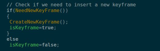
step 5: modify the call interface in the ROS node of the online camera that we wrote in the previous blog, and set the
Tcw = mpSLAM->TrackRGBD(cv_ptrRGB->image,cv_ptrD->image,cv_ptrRGB->header.stamp.toSec());
Changed to:
Tcw = mpSLAM->TrackRGBD(cv_ptrRGB->image,cv_ptrD->image,cv_ptrRGB->header.stamp.toSec(),isKeyFrame);
Since I adjusted the publishing location of Tcw, the modified function is:
void ImageGrabber::GrabRGBD(const sensor_msgs::ImageConstPtr& msgRGB,const sensor_msgs::ImageConstPtr& msgD)
{
    // Copy the ros image message to cv::Mat.
    cv_bridge::CvImageConstPtr cv_ptrRGB;
    try
    {
        cv_ptrRGB = cv_bridge::toCvShare(msgRGB);
    }
    catch (cv_bridge::Exception& e)
    {
        ROS_ERROR("cv_bridge exception: %s", e.what());
        return;
    }

    cv_bridge::CvImageConstPtr cv_ptrD;
    try
    {
        cv_ptrD = cv_bridge::toCvShare(msgD);
    }
    catch (cv_bridge::Exception& e)
    {
        ROS_ERROR("cv_bridge exception: %s", e.what());
        return;
    }

    bool  isKeyFrame =true;
    cv::Mat Tcw;
    Tcw = mpSLAM->TrackRGBD(cv_ptrRGB->image,cv_ptrD->image,cv_ptrRGB->header.stamp.toSec(),isKeyFrame);
    if (!Tcw.empty())
	{
				  //cv::Mat Twc =Tcw.inv();
				  //cv::Mat TWC=orbslam->mpTracker->mCurrentFrame.mTcw.inv();
				  cv::Mat RWC= Tcw.rowRange(0,3).colRange(0,3);
				  cv::Mat tWC= Tcw.rowRange(0,3).col(3);

				  tf::Matrix3x3 M(RWC.at<float>(0,0),RWC.at<float>(0,1),RWC.at<float>(0,2),
							      RWC.at<float>(1,0),RWC.at<float>(1,1),RWC.at<float>(1,2),
							      RWC.at<float>(2,0),RWC.at<float>(2,1),RWC.at<float>(2,2));
				  tf::Vector3 V(tWC.at<float>(0), tWC.at<float>(1), tWC.at<float>(2));

				 tf::Quaternion q;
				  M.getRotation(q);

			      tf::Pose tf_pose(q,V);

				   double roll,pitch,yaw;
				   M.getRPY(roll,pitch,yaw);
				   //cout<<"roll: "<<roll<<"  pitch: "<<pitch<<"  yaw: "<<yaw;
				  // cout<<"    t: "<<tWC.at<float>(0)<<"   "<<tWC.at<float>(1)<<"    "<<tWC.at<float>(2)<<endl;

				   if(roll == 0 || pitch==0 || yaw==0)
					return ;
				   // ------

				  std_msgs::Header header ;
				  header.stamp =msgRGB->header.stamp;
				  header.seq = msgRGB->header.seq;
				  header.frame_id="camera";

				  //cout<<"depth type: "<< depth. type()<<endl;

				  sensor_msgs::Image::ConstPtr rgb_msg = msgRGB;
				  sensor_msgs::Image::ConstPtr depth_msg=msgD;

				 geometry_msgs::PoseStamped tcw_msg;
				 tcw_msg.header=header;
				 tf::poseTFToMsg(tf_pose, tcw_msg.pose);

				 camerapath.header =header;
				 camerapath.poses.push_back(tcw_msg);
				 pub_camerapath.publish(camerapath);  //Camera trajectory
				 if( isKeyFrame)
				{
					pub_tcw.publish(tcw_msg);	                      //Tcw pose information
					pub_rgb.publish(rgb_msg);
					pub_depth.publish(depth_msg);
				}
	}
	else
	{
	  cout<<"Twc is empty ..."<<endl;
	}
}
In this way, we can release all the tracks of the camera, the key frame images and pose data.
2 write drawing thread
2.1 overall thinking
The function of the mapping thread is to receive the color map, depth map and Tcw paired data output by the pose estimation node. Then color map and depth map are spliced to build point cloud. Point cloud is maintained and displayed by pcl.
2.2 write ROS node
Create a new package called "pointcloud" mapping in ROS workspace. This package will depend on the point cloud library. Please make sure that the point cloud library has been installed on your computer.
The main function of this node is to receive the color map, depth map and Tcw pose data released by pose estimation node, then use these information to reconstruct the point cloud, and rotate it to the global coordinate system to splice the point cloud.
Part of the interface code of ROS is: all operations are implemented in the PointCloudMapper class.
int main(int argc, char **argv)
{

    std::string cameraParamFile;

    ros::init(argc, argv, "pointcloud_mapping", ros::init_options::AnonymousName);

    if(!ros::ok())
    {
	     cout<<"ros init error..."<<endl;
	    return 0;
    }


	float fx =515.2888; //Astra camera
	float cx =317.9098;
	float fy =517.6610;
	float cy =241.5734;
	float resolution =0.01;

	Mapping::PointCloudMapper mapper(fx,fy,cx,cy,resolution);;
	mapper.viewer();

	cout<<"ros shutdown ..."<<endl;
    return 0;
}
2.3 operation effect
The figure below is an effect picture running on the data set of the TUM. From the picture, it can be seen that the point cloud is obviously not aligned. I guess it is mainly because the time stamp between the depth map and the pose is not aligned. We need to use some additional methods to solve this problem.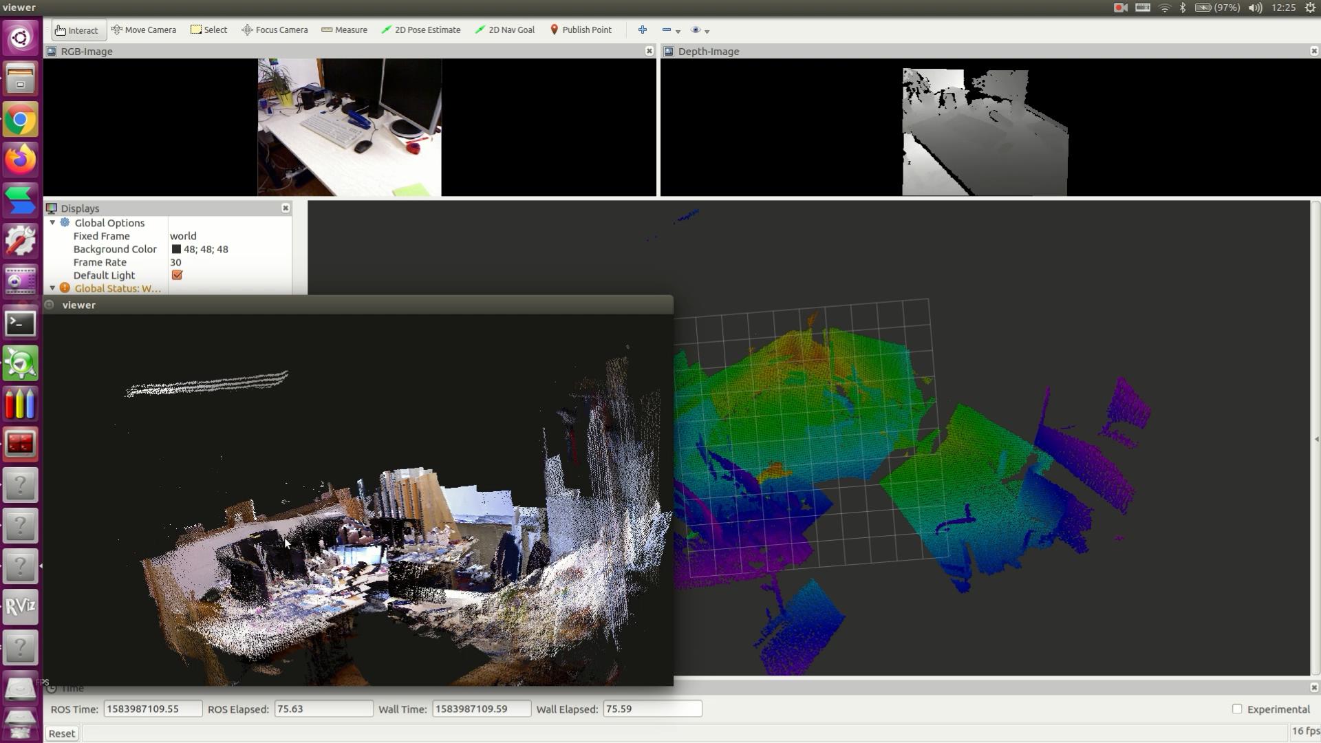
For online conversion between octree map and point cloud map in ROS, please refer to my previous blog Real time display of Octomap in ROS environment
Due to a recent article in water, I will synchronize the code to the network for you to consult after tuning. You can try this idea first.
Previous: ORB-SLAM2 online building dense point cloud (2)
If you think the article is helpful to you, please give me a compliment. O (O)
Welcome to the comment area (cenruping@vip.qq.com)

