preface
A person can go faster, and a group of people can go further. Exchange and learning plus qq:2096723956
More nanny PX4+ROS learning videos: https://b23.tv/ZeUDKqy
Share knowledge and transmit positive energy. Please point out any omissions or mistakes
PX4 firmware version: 1.11.3
PX4 separates the mixed controller logic from the actual attitude controller, which greatly improves the reusability of the code. Different models only need to define different mixed control scripts, and the core code can be universal (for example, the same set of control algorithm is used for helicopter control and multi rotor control)
The function of the hybrid controller is to convert the torque command and scalar thrust value of all three axes (roll, pitch and yaw) output by the rate controller into a separate motor thrust command or steering gear command. Finally, the output driver (such as UART, UAVCAN or PWM) scales it to the output value of the actuator, such as PWM value.
1, Mixed control script
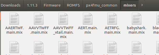
Script location:
1. Control input group
PX4 uses control input group and output group. Values in different groups have different meanings, such as attitude for core flight control or PTZ for payload. The output group is a physical bus used to control the actuator (electric control), such as FMU channel or IO channel or uavcan channel of flight control (because some electric control supports uavcan protocol). If uavcan is enabled, the main hybrid controller will be loaded into the device / dev/uavcan/esc (uavcan), otherwise it will be loaded into / dev/pwm_output0 (this device will be mapped to the IO driver on the controller with I/O board and the FMU driver on the board without I/O board), and the aux mixer file will be loaded into the standby / dev / PWM_ In output1, this file is mapped to the FMU driver on the Pixhawk controller with I/O board
Each control input group has eight standardized (- 1... + 1) command ports. The mixer defines how each of the eight input signals is mapped to eight outputs. Since there are multiple control groups (such as flight control, payload, etc.) and multiple output groups (buses), one control group can send commands to multiple output groups.
Members of different control input groups have the following meanings:
Control Group #0 (Flight Control)
0: roll (-1..1)
1: pitch (-1..1)
2: yaw (-1..1)
3: throttle (0..1 normal range, -1..1 for variable pitch / thrust reversers)
4: flaps (-1..1)
5: spoilers (-1..1)
6: airbrakes (-1..1)
7: landing gear (-1..1)
Control Group #1 (Flight Control VTOL/Alternate)
0: roll ALT (-1..1)
1: pitch ALT (-1..1)
2: yaw ALT (-1..1)
3: throttle ALT (0..1 normal range, -1..1 for variable pitch / thrust reversers)
4: reserved / aux0
5: reserved / aux1
6: reserved / aux2
7: reserved / aux3
#Control Group #2 (Gimbal)
0: gimbal roll
1: gimbal pitch
2: gimbal yaw
3: gimbal shutter
4: camera zoom
5: reserved
6: reserved
7: reserved (parachute, -1..1)
#Control Group #3 (Manual Passthrough)
0: RC roll
1: RC pitch
2: RC yaw
3: RC throttle
4: RC mode switch (Passthrough of RC channel mapped by RC_MAP_FLAPS)
5: RC aux1 (Passthrough of RC channel mapped by RC_MAP_AUX1)
6: RC aux2 (Passthrough of RC channel mapped by RC_MAP_AUX2)
7: RC aux3 (Passthrough of RC channel mapped by RC_MAP_AUX3)
Control Group #4 (Flight Control MC VIRTUAL)
0: roll ALT (-1..1)
1: pitch ALT (-1..1)
2: yaw ALT (-1..1)
3: throttle ALT (0..1 normal range, -1..1 for variable pitch / thrust reversers)
4: reserved / aux0
5: reserved / aux1
6: reserved / aux2
7: reserved / aux3
#Control Group #5 (Flight Control FW VIRTUAL)
0: roll ALT (-1..1)
1: pitch ALT (-1..1)
2: yaw ALT (-1..1)
3: throttle ALT (0..1 normal range, -1..1 for variable pitch / thrust reversers)
4: reserved / aux0
5: reserved / aux1
6: reserved / aux2
7: reserved / aux3
Control Group #6 (First Payload)
0: function 0
1: function 1
2: function 2
3: function 3
4: function 4
5: function 5
6: function 6
7: function 7
2. Syntax of mixed control script
If the mixer is used for main channel output, it must be named XXXX main. Mix, if used for auxiliary channel output, must be named XXXX aux. mix.
Multi rotor hybrid control
R: <Fuselage configuration> <Roll scale> <Pitch scaling> <Yaw scaling> <idling>
The supported multi rotor fuselage layout is as follows:
4x - X four rotor
4 + - + four rotor
6x - X six rotor
6 + - + six rotor
8x - X type eight rotor
8 + - + type eight rotor
Each roll, pitch and yaw scaling value determines the ratio of roll, pitch and yaw control to thrust control. When the calculation is performed as a floating-point operation, the value stored in the definition file is scaled by a factor of 10000, for example, the value corresponding to the scaling factor of 0.5 is 5000.
Roll, pitch and yaw inputs range from - 1.0 to 1.0, while thrust inputs range from 0.0 to 1.0. The output of each actuator is in the range of - 1.0 to 1.0.
The idle speed ranges from 0.0 to 1.0. Refers to the speed at which the motor rotates when all control inputs are zero. When the actuator is saturated, all actuator values are readjusted to limit the saturated actuator output to 1.0.
Cumulative mixed control
Cumulative hybrid control is also called Simple hybrid control. The hybrid controller combines zero or more control inputs into a single actuator output. The input is scaled, and the mixed control function sums the results before applying the output scaler. The format is as follows:
M: <Enter the number of control quantities>
O: <Negative scaling> <Positive scaling> <Offset value> <lower limit> <upper limit> <Lateral time (optional)>
The first line M: < number of input control quantities > represents several input sources, and the second line O: the scaling value is scaled by a factor of 10000; The offset value is also offset by a factor of 10000< Lateral time > is used for the actuator. If the action of the actuator changes too fast, the actuator may be damaged. For example, a < lateral time > value of 20000 will limit the rate of change of the actuator so that it takes at least 2 seconds from < lower limit > to < upper limit >.
S: <Control input group> <Index value> <Negative scaling> <Positive scaling> <Offset value> <lower limit> <upper limit>
S: Indicates the specific input source, corresponding to the first line M: < number of input control quantities >, there are several input control quantities, there are several s:. If < number of input control quantities > is zero, the hybrid controller will output a fixed < offset value > constrained by < lower limit > and < upper limit >< The control input group > value identifies the control group from which the mixer will read, and the < index value > value identifies the offset within the group. For example, control input group 0 is the vehicle attitude control group, and < index value > 0 to 3 are roll, pitch, yaw and thrust respectively.
Typical examples:
M: 2
O:      10000  10000      0 -10000  10000
S: 0 0  -6000  -6000      0 -10000  10000
S: 0 1   6500   6500      0 -10000  10000
There are two control input groups, indicating that the mixer will receive two inputs
Both positive and negative scaling are 1, the offset is zero, and the output range is - 1 to 1. If you want to reverse the PWM signal, you must change the symbol of the output scale: O: - 10000 - 10000 0 - 10000
If the row specifies the default zoom scale o: 10000 0 - 10000 10000, you can (and should) ignore the row completely
The third line S: indicates the first control input: it accepts the input of the control group #0 (flight control) and the first input (roll). It scales the scroll control input * 0.6 and restores the symbol (- 0.6 becomes - 6000 in scaling units). It does not apply offset (0) and outputs to full scale (- 1... + 1)
Helicopter hybrid control
Mixed control statement of tilt plate
H: <Number of tilt disc steering gear,3 Or 4>
T: <Throttle thrust curve, when the thrust is at 0%,25%, 50%,75%,100%Corresponding throttle value at: 0%> <25%> <50%> <75%> <100%>
P: <Total moment thrust curve, when the thrust is at 0%,25%, 50%,75%,100%Total moment value corresponding to: 0%> <25%> <50%> <75%> <100%>
The following is the mixed control of each tilt plate steering gear
S: <The installation angle of the steering gear is in degrees, and 0 degrees is the direction of the nose. From above, it is positive in the clockwise direction> <Steering arm length, 10000 equals 1. If all steering arms have the same length, the value should be 10000. The larger arm length will reduce the servo deflection, and the shorter arm will increase the servo deflection> <Zoom value, servo output by zoom value/10000 Zoom> <Offset, the value should be between-10000 and+10000 between.When the control is scaled, the offset is added> <Lower limit of control quantity> <Upper limit of control quantity>
The tail rotor of a helicopter can be controlled by a cumulative hybrid control
2, Code analysis of mixer controller
The input of the hybrid controller is the torque generated by attitude control. For example, the torque output by multiple rotors after internal angular rate control is as follows:
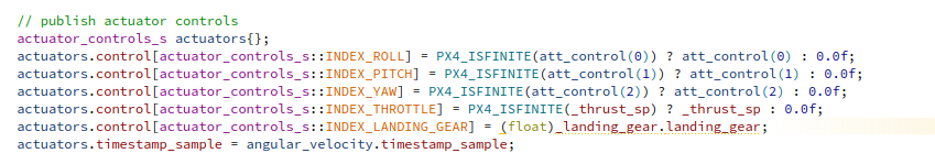
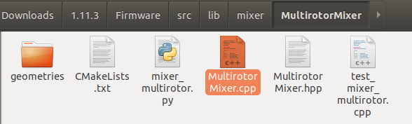
The code location of the mixer controller is as follows:
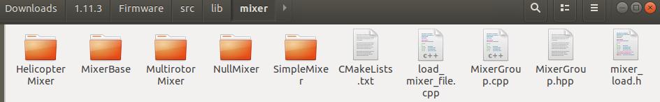
It mainly includes three types: multi rotor, helicopter and cumulative hybrid control
1. Actuator anti saturation
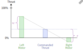
1. Lower limit saturation resistance
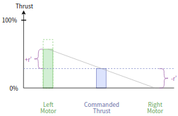
In some cases, for example, under low thrust and large roll maneuver commands, it may occur that a motor command becomes negative. This makes it impossible for the UAV to execute these commands (except for reversible motors), which is called actuator saturation. As shown below:
PX4 has two modes to solve this problem:
1. Reduce the rolling command torque to make the motor command not lower than zero (disable Airmode). In the extreme case of zero command thrust, this means that attitude correction can no longer be carried out, so the minimum thrust is always required in this mode. As shown below:
2. Increase the thrust to make all motor commands positive (enable Airmode). The biggest advantage of this is that the attitude / rate can be tracked correctly even when the throttle is low or zero. If the UAV is in good flight condition, you can enable Airmode to improve flight performance** However, this method increases the total thrust. Even if the throttle drops to zero, the aircraft may still rise** This may happen especially when the aircraft oscillates strongly due to the high P tuning gain.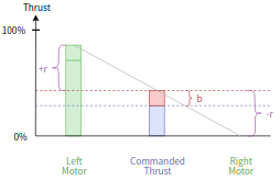
2. Upper limit saturation resistance
If the mixer is saturated in the upper limit direction, reduce the total thrust to ensure that no motor is required to provide more than 100% thrust. Anti upper saturation is independent of enabling or disabling Airmode.
2. Multi rotor hybrid control
The multi rotor hybrid controller combines four control inputs (rolling, pitching, yaw and thrust) into a group of actuator outputs to drive the motor speed controller. Code location:
unsigned
MultirotorMixer::mix(float *outputs, unsigned space)
{
If the maximum number of output channels (usually 8) is less than the number of motors, return 0
if (space < _rotor_count) {
	return 0;
}
Obtain the desired roll, pitch, yaw torque and thrust from the control input. Roll, pitch, yaw respectively take the 0,1,2 elements of the control input group 0, scale them by the scaling coefficient, and then limit them to - 1 to 1. The thrust directly takes the third element of the control input group 0, and limit them to 0 to 1
float roll    = math::constrain(get_control(0, 0) * _roll_scale, -1.0f, 1.0f);
float pitch   = math::constrain(get_control(0, 1) * _pitch_scale, -1.0f, 1.0f);
float yaw     = math::constrain(get_control(0, 2) * _yaw_scale, -1.0f, 1.0f);
float thrust  = math::constrain(get_control(0, 3), 0.0f, 1.0f);
Motor saturation reset
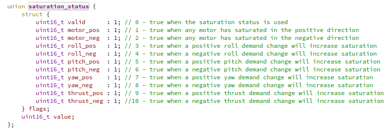
_saturation_status.value = 0;
Motor saturation member variables are defined as follows
Carry out mixed control according to the current Airmode configuration
switch (_airmode) {
case Airmode::roll_pitch:
	mix_airmode_rp(roll, pitch, yaw, thrust, outputs);
	break;

case Airmode::roll_pitch_yaw:
	mix_airmode_rpy(roll, pitch, yaw, thrust, outputs);
	break;

case Airmode::disabled:
default: // just in case: default to disabled
	mix_airmode_disabled(roll, pitch, yaw, thrust, outputs);
	break;
}
There are three mixed control modes above, corresponding to different anti actuator saturation strategies, roll_pitch and roll_pitch_ Yaws belong to the category of enabling Airmode. The difference is roll_pitch only performs anti actuator saturation treatment for roll and pitch, while yaw is controlled separately_ pitch_ Yaw performs anti actuator saturation treatment for roll, pitch and yaw. disabled means to disable Airmode. The principle of enabling and disabling Airmode has been described earlier
Apply the following thrust model, through which the PWM value can be calculated according to the thrust
thrust = (1 - _thrust_factor) * PWM + _thrust_factor * PWM^2
Shift the term and solve the univariate quadratic equation to calculate the PWM value as follows
for (unsigned i = 0; i < _rotor_count; i++) {
	if (_thrust_factor > 0.0f) {
		outputs[i] = -(1.0f - _thrust_factor) / (2.0f * _thrust_factor) + sqrtf((1.0f - _thrust_factor) *
				(1.0f - _thrust_factor) / (4.0f * _thrust_factor * _thrust_factor) + (outputs[i] < 0.0f ? 0.0f : outputs[i] /
						_thrust_factor));
	}
Scale the PWM value between idle and 1
	outputs[i] = math::constrain(_idle_speed + (outputs[i] * (1.0f - _idle_speed)), _idle_speed, 1.0f);
}
The final output is subjected to anti negative saturation and change rate limiting
Define flag bit
for (unsigned i = 0; i < _rotor_count; i++) {
	bool clipping_high = false;
	bool clipping_low_roll_pitch = false;
	bool clipping_low_yaw = false;
Here, judge whether the anti lower limit saturation is required, and set the relevant flag bit. The specific anti saturation operation is set according to the above mix_airmode_rp,mix_airmode_rpy,mix_airmode_disabled.
if (outputs[i] < _idle_speed + 0.01f) {
	if (_airmode == Airmode::disabled) {
		clipping_low_roll_pitch = true;
		clipping_low_yaw = true;

	} else if (_airmode == Airmode::roll_pitch) {
		clipping_low_yaw = true;
	}
}
Here, judge whether the output change range of each cycle needs to be limited. The judgment method is to compare whether the difference between the current output and the last output exceeds the limit. If it exceeds the limit, set it to the maximum value and set the flag bit.
if (_delta_out_max > 0.0f) {
	float delta_out = outputs[i] - _outputs_prev[i];

	if (delta_out > _delta_out_max) {
		outputs[i] = _outputs_prev[i] + _delta_out_max;
		clipping_high = true;

	} else if (delta_out < -_delta_out_max) {
		outputs[i] = _outputs_prev[i] - _delta_out_max;
		clipping_low_roll_pitch = true;
		clipping_low_yaw = true;
	}
}

		_outputs_prev[i] = outputs[i];
Update status flag bit
	update_saturation_status(i, clipping_high, clipping_low_roll_pitch, clipping_low_yaw);
}
Set the maximum value of the output variation amplitude to zero, and assign the value to this parameter before each mixed control, otherwise the amplitude will not be limited
_delta_out_max = 0.0f;
return
	return _rotor_count;
}
3. Helicopter hybrid control
file location
unsigned
HelicopterMixer::mix(float *outputs, unsigned space)
{
Judge whether the number of motors and steering gear exceeds the maximum number of output ports. If so, return 0_ mixer_info.control_count is the number of tilt steering gear, plus one is the output of the main propeller.
if (space < _mixer_info.control_count + 1u) {
	return 0;
}
Calculate the corresponding throttle / total torque value under the current expected thrust according to the set throttle / total torque curve parameters of 0%, 25%, 50%, 75% and 100% (set in the hybrid control script)
Obtain the desired thrust value
float thrust_cmd = get_control(0, 3);
Calculate the corresponding thrust interval coefficient
int idx = (thrust_cmd / 0.25f);
	if (idx < 0) {
		idx = 0;
	} else if (idx > HELI_CURVES_NR_POINTS - 2) {
		idx = HELI_CURVES_NR_POINTS - 2;
	}
Calculate the throttle according to the thrust and throttle thrust curve parameters
float tg = (_mixer_info.throttle_curve[idx + 1] - _mixer_info.throttle_curve[idx]) / 0.25f;
float to = (_mixer_info.throttle_curve[idx]) - (tg * idx * 0.25f);
float throttle = constrain(2.0f * (tg * thrust_cmd + to) - 1.0f, -1.0f, 1.0f);
Calculate the throttle torque according to the thrust and total torque thrust curve parameters
float pg = (_mixer_info.pitch_curve[idx + 1] - _mixer_info.pitch_curve[idx]) / 0.25f;
float po = (_mixer_info.pitch_curve[idx]) - (pg * idx * 0.25f);
float collective_pitch = constrain((pg * thrust_cmd + po), -0.5f, 0.5f);
Obtain the desired roll / pitch torque
float roll_cmd = get_control(0, 0);
float pitch_cmd = get_control(0, 1);
Assign the desired throttle directly to the main rotor motor
outputs[0] = throttle;
Calculate the output of tilt disc steering gear according to helicopter dynamics
for (unsigned i = 0; i < _mixer_info.control_count; i++) {
	outputs[i + 1] = collective_pitch
			 + cosf(_mixer_info.servos[i].angle) * pitch_cmd * _mixer_info.servos[i].arm_length
			 - sinf(_mixer_info.servos[i].angle) * roll_cmd * _mixer_info.servos[i].arm_length;
	outputs[i + 1] *= _mixer_info.servos[i].scale;
	outputs[i + 1] += _mixer_info.servos[i].offset;
	outputs[i + 1] = constrain(outputs[i + 1], _mixer_info.servos[i].min_output, _mixer_info.servos[i].max_output);
}
return
	return _mixer_info.control_count + 1;
}
4. Simple accumulation and mixed control
unsigned
SimpleMixer::mix(float *outputs, unsigned space)
{
	float sum = 0.0f;

	if (_pinfo == nullptr) {
		return 0;
	}
Returns 0 if the available output port is less than 1
if (space < 1) {
	return 0;
}
The callback function is used to obtain the value input of the member in the corresponding control input group.
for (unsigned i = 0; i < _pinfo->control_count; i++) {
	float input = 0.0f;
	_control_cb(_cb_handle,
		    _pinfo->controls[i].control_group,
		    _pinfo->controls[i].control_index,
		    input);
Scale the input and add it to the sum
	sum += scale(_pinfo->controls[i].scaler, input);
}
Output scaling. Scaling here is to scale the total final output. The above scaling is to scale the members of the control input group.
*outputs = scale(_pinfo->output_scaler, sum);
Output variation amplitude limiting
if (_dt > FLT_EPSILON && _pinfo->slew_rate_rise_time > FLT_EPSILON) {
Calculate the maximum amplitude of output change in this cycle, because the change range is [- 1,1], so multiply by 2
const float output_delta_max = 2.0f * _dt / _pinfo->slew_rate_rise_time;
Limiting amplitude
	float delta_out = *outputs - _output_prev;
	if (delta_out > output_delta_max) {
		*outputs = _output_prev + output_delta_max;
	} else if (delta_out < -output_delta_max) {
		*outputs = _output_prev - output_delta_max;
	}
}
Will_ dt is set to zero to ensure that the value is assigned during each cycle_ dt, otherwise the output change amplitude limit will not be carried out
_dt = 0.f;
return
	_output_prev = *outputs;
	return 1;
}
3, PWM output code analysis
Code location
 Initialize the state machine and reset the unlocking time
void output_limit_init(output_limit_t *limit)
{
	limit->state = OUTPUT_LIMIT_STATE_INIT;
	limit->time_armed = 0;
	limit->ramp_up = true;
}
Specific calculation of PWM output value
void output_limit_calc(const bool armed, const bool pre_armed, const unsigned num_channels, const uint16_t reverse_mask,
		       const uint16_t *disarmed_output, const uint16_t *min_output, const uint16_t *max_output,
		       const float *output, uint16_t *effective_output, output_limit_t *limit)
{
Output PWM according to different states, switch the state according to the actual situation, and set the state flag bit limit - > state
There are four states:
| OUTPUT_LIMIT_STATE_INIT | Initialization status |
|---|---|
| OUTPUT_LIMIT_STATE_OFF | Locked state |
| OUTPUT_LIMIT_STATE_RAMP | Transition state |
| OUTPUT_LIMIT_STATE_ON | On state |
The lock value (generally 900us) will be output in the initialization state and lock state. In the transition state, the PWM will slowly increase from the lock value to the minimum value (such as 1000us) within a certain time. After the transition is completed, it will enter the on state. In the on state, it can be output directly in the effective signal range (such as 1000us to 2000us). After power on, the electric regulator usually gives the locking value first, then calls the president of the electric regulator, then enters the transition state, and finally enters the on state to control the motor. If the flight control directly outputs a valid signal after the electric dispatcher is powered on or jumps directly from the locking signal to a valid signal, the electric dispatcher will enter the alarm mode (urgent "beep beep" alarm sound)
switch (limit->state) {
In the initial state, after init_ TIME_ Automatically enter the locked state after us
case OUTPUT_LIMIT_STATE_INIT:
	if (armed) {
		if (limit->time_armed == 0) {
			limit->time_armed = hrt_absolute_time();
		}
		if (hrt_elapsed_time(&limit->time_armed) >= INIT_TIME_US) {
			limit->state = OUTPUT_LIMIT_STATE_OFF;
		}
	}
	break;
If it is unlocked in the locked state, it will enter the transition state and record the current time as the start transition time
case OUTPUT_LIMIT_STATE_OFF:
	if (armed) {
		if (limit->ramp_up) {
			limit->state = OUTPUT_LIMIT_STATE_RAMP;
		} else {
			limit->state = OUTPUT_LIMIT_STATE_ON;
		}
		limit->time_armed = hrt_absolute_time();
	}
	break;
If it is locked in the transition state, it will enter the locked state, otherwise it will enter the open state after the transition
case OUTPUT_LIMIT_STATE_RAMP:
	if (!armed) {
		limit->state = OUTPUT_LIMIT_STATE_OFF;
	} else if (hrt_elapsed_time(&limit->time_armed) >= RAMP_TIME_US) {
		limit->state = OUTPUT_LIMIT_STATE_ON;
	}
	break;
In the open state, if it is locked, it will enter the locked state
case OUTPUT_LIMIT_STATE_ON:
	if (!armed) {
		limit->state = OUTPUT_LIMIT_STATE_OFF;
	}
	break;
default:
	break;
}
/* if the system is pre-armed, the limit state is temporarily on,
 * as some outputs are valid and the non-valid outputs have been
 * set to NaN. This is not stored in the state machine though,
 * as the throttle channels need to go through the ramp at
 * regular arming time.
 */
Output PWM according to status
unsigned local_limit_state = limit->state;
if (pre_armed) {
	local_limit_state = OUTPUT_LIMIT_STATE_ON;
}
unsigned progress;
Output lock value in lock and initial state
switch (local_limit_state) {
case OUTPUT_LIMIT_STATE_OFF:
case OUTPUT_LIMIT_STATE_INIT:
	for (unsigned i = 0; i < num_channels; i++) {
		effective_output[i] = disarmed_output[i];
	}
	break;
In the transition state, the current output is calculated according to the transition time and the minimum output value
case OUTPUT_LIMIT_STATE_RAMP: {
Calculate the time from the transition state to the present
hrt_abstime diff = hrt_elapsed_time(&limit->time_armed);
Calculate the ratio of the elapsed time to the set transition time and multiply it by the coefficient PROGRESS_INT_SCALING
progress = diff * PROGRESS_INT_SCALING / RAMP_TIME_US;
If the scale is greater than 1, it is set to 1.
if (progress > PROGRESS_INT_SCALING) {
	progress = PROGRESS_INT_SCALING;
}
The unavailable output is set to the lock value
for (unsigned i = 0; i < num_channels; i++) {
	float control_value = output[i];
	if (!PX4_ISFINITE(control_value)) {
		effective_output[i] = disarmed_output[i];
		continue;
	}
Set lock value
uint16_t ramp_min_output;
if (disarmed_output[i] > 0) {
	unsigned disarmed = disarmed_output[i];
If the lock value is greater than the minimum output value, set the minimum output value as the lock value
if (disarmed > min_output[i]) {
	disarmed = min_output[i];
}
Calculate the difference between the minimum output and the lock setting, and calculate the minimum PWM value under the current transition state according to the time proportion. This minimum PWM output value is the value that increases linearly from the lock value to the minimum value within the transition time.
	unsigned disarmed_min_diff = min_output[i] - disarmed;
	ramp_min_output = disarmed + (disarmed_min_diff * progress) / PROGRESS_INT_SCALING;
}
If the lock value is not set, the minimum value is output directly
else {
					ramp_min_output = min_output[i];
				}
If the reverse flag bit is 1 (through parameter setting), the output is reversed
if (reverse_mask & (1 << i)) {
	control_value = -1.0f * control_value;
}
The final output is calculated according to the current control quantity (- 1 to 1) and the minimum PWM output value and the maximum PWM output value
effective_output[i] = control_value * (max_output[i] - ramp_min_output) / 2 + (max_output[i] + ramp_min_output) / 2;
Prevent invalid output
		if (effective_output[i] < ramp_min_output) {
			effective_output[i] = ramp_min_output;
		} else if (effective_output[i] > max_output[i]) {
			effective_output[i] = max_output[i];
		}
	}
}
break;
In the on state, control directly according to the current control quantity_ Value (- 1 to 1) and min_output and max_output outputs the final PWM wave. The principle is the same as that of the transition state, but the minimum value is fixed and does not change with time. The output PWM range is between the minimum value and the maximum value.
	case OUTPUT_LIMIT_STATE_ON:
		for (unsigned i = 0; i < num_channels; i++) {
			float control_value = output[i];
			if (!PX4_ISFINITE(control_value)) {
				effective_output[i] = disarmed_output[i];
				continue;
			}
			if (reverse_mask & (1 << i)) {
				control_value = -1.0f * control_value;
			}
			effective_output[i] = control_value * (max_output[i] - min_output[i]) / 2 + (max_output[i] + min_output[i]) / 2;
			if (effective_output[i] < min_output[i]) {
				effective_output[i] = min_output[i];
			} else if (effective_output[i] > max_output[i]) {
				effective_output[i] = max_output[i];
			}
		}
		break;
	default:
		break;
	}
}