python double target localization and reconstruction
As mentioned above: a course assignment of machine vision is to collect a group of binocular images and complete the relevant processes of stereo vision: including camera calibration (internal and external parameters), distortion correction, basic matrix estimation, parallax map calculation (image correction is required first), recovery and drawing 3D point coordinates. The code on the Internet is basically based on checkerboard. You don't understand it at first. When you copy too much, you will understand it naturally. The principle is not introduced in detail. I will briefly introduce the implementation process and the problems encountered. The reconstruction of the last part can not ensure accuracy, because the reconstructed image is simply not good-looking! The code references in this article have been marked in the reference link, and some parts have been changed and supplemented.
For learning purposes only!
1. Image acquisition and pre experiment
1.1 image
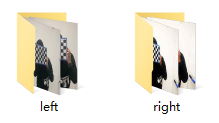
Collect a set of binocular images. In this step, the elder martial brother will appear in the mirror. I use two mobile phones to shoot at a fixed position at the same time, so as to get 10 pairs of images. That is, the left and right mobile phones are aligned together, and then press the shutter at the same time. There must be a lot of error in this operation.
1.2 matlab pre experiment
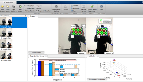
Initial use CV2 Findchess board corners did not detect any corners, and the detection time was long. Therefore, first use the toolbox of matlab for pre experiment (refer to link 3). The following results are obtained, indicating that the data can still be detected. The data in the figure has been screened and several images with large errors have been removed. By observing the results and checking the data, we know that this function can only detect internal corners, so the size of the chessboard given by my image should be (7,5), so pay attention to changing the parameters.
1.3 python pre experiment
Read all the images in the left and right folders, detect their corners, record the images that can be detected, and obtain the corresponding image pairs. Finally, 4 pairs of images can be obtained (4 pairs can be obtained out of 10 pairs. Fortunately, elder martial brother loves the mirror). In the following code, truth looks at the file name that can detect corners.
all_images = glob('./datas/*/*.jpg')

truth = []
def test1(image):
    img_l = cv2.imread(image)
    gray_l = cv2.cvtColor(img_l, cv2.COLOR_BGR2GRAY)
    ret_l, corners_l = cv2.findChessboardCorners(gray_l, (7, 5), None)
    if ret_l:
        truth.append(image)

for i in all_images:
    print(f'-------------processing {i}--------------')
    test1(i)
print(truth)
2. Camera calibration and parameter solution
2.1 determination of coordinate system and coordinates
- Define the world coordinate system, that is, 3D coordinates
- Carry out corner detection on the two images of the left and right cameras and record their coordinates
- Camera calibration
Its principle is simply the mutual transformation of world coordinate system, camera coordinate system and image coordinate system. The transformation is solved by matrix. How to solve it is through some calculation methods, such as SVD through corresponding points.
The calibration process is divided into two parts: one is to convert from the world coordinate system to the camera coordinate system, and the other is to convert from the camera coordinate system to the image coordinate system (refer to link 7). If you know a point X in the camera coordinate system (a point in the real three-dimensional world) and the corresponding point in the image plane coordinate system is x ', the conversion from the camera coordinate system to the image plane coordinate system can be obtained from a transformation matrix, which is the internal parameter offset of the camera. The transformation from world coordinate system to camera coordinate system is the transformation from three-dimensional space to three-dimensional space. Generally speaking, it needs a translation operation and a rotation operation to complete this transformation.
Distortion is an offset of linear projection. In short, straight line projection is a straight line in the scene projected onto the picture and maintained as a straight line. Distortion can generally be divided into two categories, including radial distortion and tangential distortion. For distortion correction, we can use the transformation matrix obtained from two camera coordinate systems to correct.
Through this step, we can get the coordinates and distance in the two-dimensional camera coordinate system, including two camera internal parameters, the basic matrix and the rotation translation matrix.
The parameter results are as follows:
- M1: camera matrix of the first camera
- d1: distortion vector of the first camera
- M2: camera matrix of the second camera
- d2: distortion vector of the second camera
- R: Rotation matrix between the first and second cameras
- T: Translation matrix
- E. F: basic matrix
2.2 solution parameters
- Through the parameters obtained in step 2.1, the internal parameters, distortion vector and basic matrix of the two cameras, and the rotation matrix and translation matrix between the two cameras are calculated
- Through the parameters obtained in the previous step, the correction transformation matrix of the two cameras, the projection matrix in the new coordinate system and the depth difference mapping matrix can be obtained
After remap reconstruction, the possible image is black, because the parameter alpha in the binocular correction function stereocorrect has an impact on the result of the matrix, so it needs to be debugged to get a high-quality reconstructed image.
The parameter results are as follows:
- R1: correction transformation matrix (rotation matrix) of the first camera
- R2: correction transformation matrix (rotation matrix) of the second camera
- P1: projection matrix of the first camera in the new coordinate system
- P2: projection matrix of the second camera in the new coordinate system
- Q: Depth difference mapping matrix
3. Parallax map calculation
This part directly borrows link 3 The explanation of the code in is also relatively clear and easy to understand. To put it simply, through step 2.2, the matrix of mutual conversion between camera A and camera B and the projection matrix projected to the two-dimensional plane (new coordinate system) can be obtained. The new coordinates can be obtained through matrix multiplication and the pixel can be assigned. Function: CV2 remap
The obtained parallax map may be white (the projection is particularly shallow), and the parameters need to be adjusted. I have increased its sigma.
# Parallax map calculation
def depth_map(imgL, imgR, sigma=1.3):
    """ Depth map calculation. Works with SGBM and WLS. Need rectified images, returns depth map ( left to right disparity ) """
    # SGBM Parameters -----------------
    window_size = 3  # wsize default 3; 5; 7 for SGBM reduced size image; 15 for SGBM full size image (1300px and above); 5 Works nicely

    left_matcher = cv2.StereoSGBM_create(
        minDisparity=-1,
        numDisparities=5*16,  # max_disp has to be dividable by 16 f. E. HH 192, 256
        blockSize=window_size,
        P1=8 * 3 * window_size,
        # wsize default 3; 5; 7 for SGBM reduced size image; 15 for SGBM full size image (1300px and above); 5 Works nicely
        P2=32 * 3 * window_size,
        disp12MaxDiff=12,
        uniquenessRatio=10,
        speckleWindowSize=50,
        speckleRange=32,
        preFilterCap=63,
        mode=cv2.STEREO_SGBM_MODE_SGBM_3WAY
    )
    right_matcher = cv2.ximgproc.createRightMatcher(left_matcher)
    # FILTER Parameters
    lmbda = 80000
    visual_multiplier = 6

    wls_filter = cv2.ximgproc.createDisparityWLSFilter(matcher_left=left_matcher)
    wls_filter.setLambda(lmbda)

    wls_filter.setSigmaColor(sigma)
    displ = left_matcher.compute(imgL, imgR)  # .astype(np.float32)/16
    dispr = right_matcher.compute(imgR, imgL)  # .astype(np.float32)/16
    displ = np.int16(displ)
    dispr = np.int16(dispr)
    filteredImg = wls_filter.filter(displ, imgL, None, dispr)  # important to put "imgL" here!!!

    filteredImg = cv2.normalize(src=filteredImg, dst=filteredImg, beta=0, alpha=255, norm_type=cv2.NORM_MINMAX);
    filteredImg = np.uint8(filteredImg)

    return filteredImg
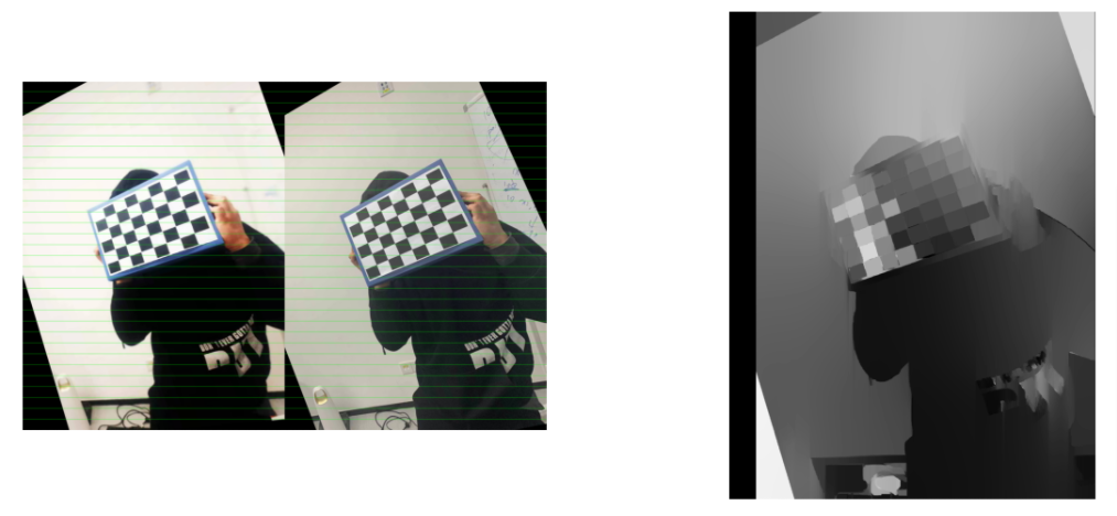
Merge each pair of images after proofreading, draw lines to view the results, and display them together with the parallax map. The right image is a parallax image, only one image is captured, and the code displays them all.
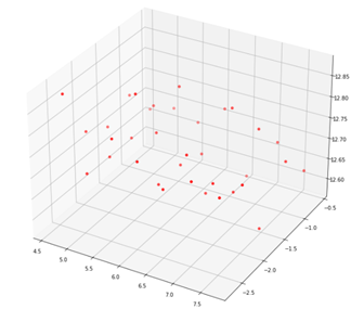
4. Reconstruct 3D points
This part adopts CV2 Trigulatepoints function. When the trigulatepoints function obtains 3d points, they are in homogeneous coordinates, and points is [ x , y , z , w ] [x, y, z, w] [x,y,z,w], w w w represents the ratio of homogeneous, and the result should be [ x / w , y / w , z / w ] [x/w, y/w, z/w] [x/w,y/w,z/w]
5. Reference links
- matlab binocular calibration (detailed process)
- https://github.com/bvnayak/stereo_calibration (some changes and supplements have been made on the basis of this code)
- Binocular stereo vision I: calibration and correction (the part of the code that draws more lessons is worth learning)
- Python computer vision - Zhang's camera internal parameter calibration
- [Python computer vision programming] Chapter 5 multi view geometry
- And the PPT of the course
- Camera calibration (parts with more principles)
6. CODE
The process of putting code directly into calculation
- Basic function
import os
import cv2
import numpy as np
from glob import glob
import matplotlib.pyplot as plt

class StereoCalibration():
    def __init__(self, filepath):

        self.criteria = (cv2.TERM_CRITERIA_EPS + cv2.TERM_CRITERIA_MAX_ITER, 30, 0.001)

        # prepare object points, like (0,0,0), (1,0,0), (2,0,0) ....,(6,5,0)
        self.objp = np.zeros((7*5, 3), np.float32)
        self.objp[:, :2] = np.mgrid[0:7, 0:5].T.reshape(-1, 2)

        # Arrays to store object points and image points from all the images.
        self.objpoints = []  # 3d point in real world space
        self.imgpoints_l = []  # 2d points in image plane.
        self.imgpoints_r = []  # 2d points in image plane.

        self.filepath = filepath
        self.read_images()

    def read_images(self):
        images_right = glob(self.filepath + 'right/[4|6|8].jpg') + ['./datas/right/11.jpg']
        images_left = glob(self.filepath + 'left/[4|6|8].jpg') + ['./datas/left/11.jpg']

        for i, fname in enumerate(images_right):
            img_l = cv2.imread(images_left[i])
            img_r = cv2.imread(images_right[i])

            gray_l = cv2.cvtColor(img_l, cv2.COLOR_BGR2GRAY)
            gray_r = cv2.cvtColor(img_r, cv2.COLOR_BGR2GRAY)

            # Find the chess board corners
            ret_l, corners_l = cv2.findChessboardCorners(gray_l, (7, 5), None)
            ret_r, corners_r = cv2.findChessboardCorners(gray_r, (7, 5), None)

            # If found, add object points, image points (after refining them)


            if ret_l and ret_r:

                self.objpoints.append(self.objp)

                rt = cv2.cornerSubPix(gray_l, corners_l, (5, 5), (-1, -1), self.criteria)
                self.imgpoints_l.append(corners_l)

                rt = cv2.cornerSubPix(gray_r, corners_r, (5, 5), (-1, -1), self.criteria)
                self.imgpoints_r.append(corners_r)
            else:
                print('Couldn\'t be found')

            img_shape = gray_l.shape[::-1]

        rt, self.M1, self.d1, self.r1, self.t1 = cv2.calibrateCamera(self.objpoints, self.imgpoints_l, img_shape, None, None)
        rt, self.M2, self.d2, self.r2, self.t2 = cv2.calibrateCamera(self.objpoints, self.imgpoints_r, img_shape, None, None)

        self.camera_model = self.stereo_calibrate(img_shape)

    def stereo_calibrate(self, dims):

        h, w = dims

        flags = 0
        # If this flag is set, the input cameraMatrix and distCoeffs will be fixed, and only R, t, e and F will be solved
        flags |= cv2.CALIB_FIX_INTRINSIC
        # Start the iteration with the initial value of cameraMatrix and distCoeffs provided by the user
        flags |= cv2.CALIB_USE_INTRINSIC_GUESS
        # The focal length is not changed during the iteration
        flags |= cv2.CALIB_FIX_FOCAL_LENGTH
        # The tangential distortion remains zero
        flags |= cv2.CALIB_ZERO_TANGENT_DIST


        stereocalib_criteria = (cv2.TERM_CRITERIA_MAX_ITER + cv2.TERM_CRITERIA_EPS, 100, 1e-5)
        ret, M1, d1, M2, d2, R, T, E, F = cv2.stereoCalibrate(
            self.objpoints,
            self.imgpoints_l,
            self.imgpoints_r,
            self.M1,
            self.d1,
            self.M2,
            self.d2,
            dims,
            criteria=stereocalib_criteria,
            flags=flags
        )

        camera_model = dict([
            ('M1', M1),
            ('M2', M2),
            ('dist1', d1),
            ('dist2', d2),
            ('rvecs1', self.r1),
            ('rvecs2', self.r2),
            ('R', R),
            ('T', T),
            ('E', E),
            ('F', F),
            ('dim', (h, w))
        ])

        return camera_model

    def rectify(self, camera_model):

        M1, d1, M2, d2, R, T =  camera_model.get('M1'), camera_model.get('d1'), camera_model.get('M2'), camera_model.get('d2'), camera_model.get('R'), camera_model.get('T')

        # Binocular correction alpha=-1, 0, 0.9
        R1, R2, P1, P2, Q, validPixROI1, validPixROI2 = cv2.stereoRectify(M1, d1, M2, d2, camera_model.get('dim'), R, T, alpha=-1)
        print('stereo rectify done...')

        # Get mapping transformation
        stereo_left_mapx, stereo_left_mapy = cv2.initUndistortRectifyMap(M1, d1, R1, P1, camera_model.get('dim'), cv2.CV_32FC1)
        stereo_right_mapx, stereo_right_mapy = cv2.initUndistortRectifyMap(M2, d2, R2, P2, camera_model.get('dim'), cv2.CV_32FC1)
        print('initUndistortRectifyMap done...')

        rectify_model = dict([
            ('R1', R1),
            ('R2', R2),
            ('P1', P1),
            ('P2', P2),
            ('Q', Q),
            ('stereo_left_mapx', stereo_left_mapx),
            ('stereo_left_mapy', stereo_left_mapy),
            ('stereo_right_mapx', stereo_right_mapx),
            ('stereo_right_mapy', stereo_right_mapy)
        ])

        return rectify_model

# Parallax map calculation
# Omitted, copy part 3

# Line drawing function
def drawLine(img, num=16):
    h, w, _ = img.shape
    for i in range(0, h, h // num):
        cv2.line(img, (0, i), (w, i), (0, 255, 0), 1, 8)
    return img
- Create the object and get the basic parameters
filepath = 'X:/Notebook/HW/CV/datas/'
cal_data = StereoCalibration(filepath)
# Get camera parameters
camera_model = cal_data.camera_model
# Get the correction parameters
rectify_model = cal_data.rectify(camera_model)
- Visualization results
stereo_left_mapx, stereo_left_mapy = rectify_model.get('stereo_left_mapx'), rectify_model.get('stereo_left_mapy')
stereo_right_mapx, stereo_right_mapy = rectify_model.get('stereo_right_mapx'), rectify_model.get('stereo_right_mapy')

# See if the grid is aligned and display the parallax map
plt.figure(figsize=(20,40))
num = 1
for i in range(len(left_images)):
    left_img = cv2.imread(left_images[i])
    right_img = cv2.imread(right_images[i])

    frame0 = cv2.remap(right_img, stereo_right_mapx, stereo_right_mapy, cv2.INTER_LINEAR, cv2.BORDER_CONSTANT)
    frame1 = cv2.remap(left_img, stereo_left_mapx, stereo_left_mapy, cv2.INTER_LINEAR, cv2.BORDER_CONSTANT)
    gray_left = cv2.cvtColor(frame0, cv2.COLOR_BGR2GRAY)
    gray_right = cv2.cvtColor(frame1, cv2.COLOR_BGR2GRAY)
    img = np.concatenate((frame0, frame1), axis=1).copy()
    img = drawLine(img, 32)
    plt.subplot(len(left_images), 2, num)
    plt.axis('off')
    plt.imshow(img[...,::-1])
    num += 1

    disparity_image = depth_map(gray_left, gray_right, sigma=2.0)
    plt.subplot(len(left_images), 2, num)
    plt.axis('off')
    plt.imshow(disparity_image, cmap='gray')
    num += 1
#     break
- restructure
pls = [np.array(i) for i in cal_data.imgpoints_l]
prs = [np.array(i) for i in cal_data.imgpoints_r]

# Take a pair of two-dimensional coordinate points of the image
ptl, ptr = pls[0], prs[0]
P1 = rectify_model.get('P1')
P2 = rectify_model.get('P2')

points = cv2.triangulatePoints(P1,P2,ptl,ptr)
coodinates_x = points[0] / points[-1]
coodinates_y = points[1] / points[-1]
coodinates_z = points[2] / points[-1]

# Convert to the form of three-dimensional coordinates. The direct reshape result is incorrect
coodinates = np.array([[i,j,k] for i,j,k in zip(coodinates_x, coodinates_y, coodinates_z)])

fig = plt.figure(figsize=(12,12))
ax = fig.add_subplot(111, projection='3d')

plt.cla()
coodinates_x, coodinates_y, coodinates_z
ax.scatter(coodinates[:, 0], coodinates[:, 1], coodinates[:, 2], color='red')
plt.draw()
plt.show()