Encoder programming is based on STM32F407IG, and the pre basic knowledge is timer input capture.
Detailed explanation of principle
The types of encoders include incremental encoder, absolute encoder and hybrid absolute encoder.
This experiment uses incremental encoder
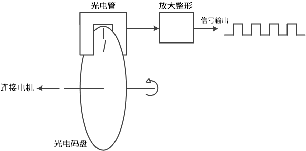
The schematic diagram of the basic encoder is shown in the figure below. Rotary encoder is mostly composed of code disk, photoelectric detection device and signal processing circuit. The code disk is engraved with several circles of wire slots, which are equidistant and transparent. When the code disk rotates, it will periodically pass through and block the light from the photoelectric detection device, so that the detection device will periodically generate several electrical signals. However, these electrical signals are usually weak, so a set of processing circuit needs to be added to amplify and shape the signal, and finally shape the signal into a pulse signal and output it to the outside. Basic schematic diagram of encoder
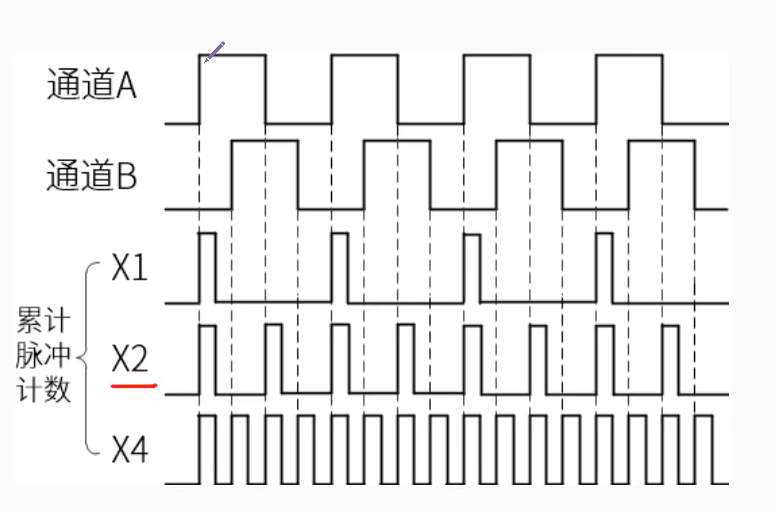
Both incremental encoders have A and B channel signal output, which is because there are two cycles of trunking on the code disk of the incremental encoder, and the two cycles of trunking will be staggered by A certain angle, which will make the two-phase signals output by the photoelectric detection device differ by 1 / 4 cycle (90 °).
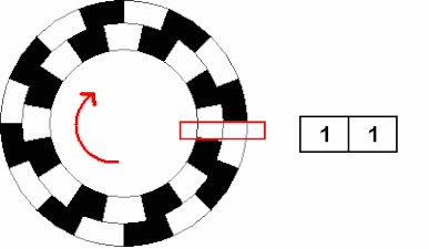
The purpose is to judge the movement direction according to the change order of the two-phase signals, record the number of output pulses, know the displacement, and get the speed through the frequency of the output signal.
The use of quadruple frequency technology in signal acquisition is to increase the resolution
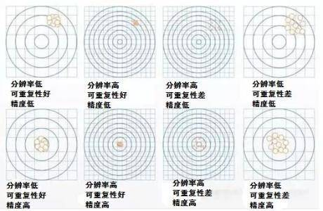
Resolution: refers to the smallest unit that the encoder can distinguish.
Accuracy refers to the maximum error between each reading of the encoder and the actual position of the rotating shaft, which is usually expressed in angle, angular minute or angular second.
The resolution is increased by four times through frequency division, and the accuracy does not change, so the accuracy is increased. Accuracy is determined by resolution and accuracy.
Code explanation
/**
  * @brief  Configure TIMx encoder mode
  * @param  nothing
  * @retval nothing
  */
static void TIM_Encoder_Init(void)
{
  TIM_Encoder_InitTypeDef Encoder_ConfigStructure;

  /* Enable encoder interface clock */
  ENCODER_TIM_CLK_ENABLE();

  /* Timer initialization settings */
  TIM_EncoderHandle.Instance = ENCODER_TIM;
  //When the value of the acquisition prescaler is 0, it means that the acquisition is performed for each edge
  TIM_EncoderHandle.Init.Prescaler = 0;
  //Count up
  TIM_EncoderHandle.Init.CounterMode = TIM_COUNTERMODE_UP;
  //The total number of times to capture a cycle is 65535
  TIM_EncoderHandle.Init.Period = 65535;
  //No frequency division
  TIM_EncoderHandle.Init.ClockDivision = TIM_CLOCKDIVISION_DIV1;
  TIM_EncoderHandle.Init.AutoReloadPreload = TIM_AUTORELOAD_PRELOAD_DISABLE;

  /* Set encoder frequency multiplier */
  Encoder_ConfigStructure.EncoderMode = ENCODER_MODE;
  /* Encoder interface channel 1 is set to start at the rising edge*/
  Encoder_ConfigStructure.IC1Polarity = TIM_ICPOLARITY_RISING;
  //Encoder polarity setting, no tube if there is no reverse direction
  Encoder_ConfigStructure.IC1Selection = TIM_ICSELECTION_DIRECTTI;
  //No frequency division
  Encoder_ConfigStructure.IC1Prescaler = TIM_ICPSC_DIV1;
  Encoder_ConfigStructure.IC1Filter = 0;
  /* Encoder interface channel 2 setting */
  Encoder_ConfigStructure.IC2Polarity = TIM_ICPOLARITY_RISING;
  Encoder_ConfigStructure.IC2Selection = TIM_ICSELECTION_DIRECTTI;
  Encoder_ConfigStructure.IC2Prescaler = TIM_ICPSC_DIV1;
  Encoder_ConfigStructure.IC2Filter = 0;
  /* Initialize encoder interface */
  HAL_TIM_Encoder_Init(&TIM_EncoderHandle, &Encoder_ConfigStructure);

  /* Reset counter */
  __HAL_TIM_SET_COUNTER(&TIM_EncoderHandle, 0);

  /* Clear interrupt flag bit */
  __HAL_TIM_CLEAR_IT(&TIM_EncoderHandle,TIM_IT_UPDATE);
  /* The update event of the enable timer is interrupted */
  __HAL_TIM_ENABLE_IT(&TIM_EncoderHandle,TIM_IT_UPDATE);
  /* Set update event request source as: counter overflow */
  __HAL_TIM_URS_ENABLE(&TIM_EncoderHandle);

  /* Set interrupt priority */
  HAL_NVIC_SetPriority(ENCODER_TIM_IRQn, 0, 1);
  /* Enable timer interrupt */
  HAL_NVIC_EnableIRQ(ENCODER_TIM_IRQn);

  /* Enable encoder interface */
  HAL_TIM_Encoder_Start(&TIM_EncoderHandle, TIM_CHANNEL_ALL);
}
/**
  * @brief  Encoder interface pin initialization
  * @param  nothing
  * @retval nothing
  */
static void Encoder_GPIO_Init(void)
{
  GPIO_InitTypeDef GPIO_InitStruct = {0};

  /* Timer channel pin port clock enable */
  ENCODER_TIM_CH1_GPIO_CLK_ENABLE();
  ENCODER_TIM_CH2_GPIO_CLK_ENABLE();

  /**TIM3 GPIO Configuration
  PC6     ------> TIM3_CH1
  PC7     ------> TIM3_CH2
  */
  /* Set input type */
  GPIO_InitStruct.Mode = GPIO_MODE_AF_OD;
  /* Set pull-up */
  GPIO_InitStruct.Pull = GPIO_PULLUP;
  /* Set pin rate */
  GPIO_InitStruct.Speed = GPIO_SPEED_FREQ_HIGH;

  /* Select the GPIO pin to control */
  GPIO_InitStruct.Pin = ENCODER_TIM_CH1_PIN;
  /* Set reuse */
  GPIO_InitStruct.Alternate = ENCODER_TIM_CH1_GPIO_AF;
  /* Call the above GPIO function library_ Initstructure initialize GPIO */
  HAL_GPIO_Init(ENCODER_TIM_CH1_GPIO_PORT, &GPIO_InitStruct);

  /* Select the GPIO pin to control */
  GPIO_InitStruct.Pin = ENCODER_TIM_CH2_PIN;
  /* Set reuse */
  GPIO_InitStruct.Alternate = ENCODER_TIM_CH2_GPIO_AF;
  /* Call the library function and use the GPIO configured above_ Initstructure initialize GPIO */
  HAL_GPIO_Init(ENCODER_TIM_CH2_GPIO_PORT, &GPIO_InitStruct);
}
/**
  * @brief  Encoder interface initialization
  * @param  nothing
  * @retval nothing
  */
void Encoder_Init(void)
{
  Encoder_GPIO_Init();    /* Pin initialization */
  TIM_Encoder_Init();     /* Configure encoder interface */
}
. h file
#ifndef __BSP_ENCOEDER_H
#define	__BSP_ENCOEDER_H

#include "stm32f4xx.h"

/* Timer selection */
#define ENCODER_TIM                            TIM3
#define ENCODER_TIM_CLK_ENABLE()  				     __HAL_RCC_TIM3_CLK_ENABLE()

/* Timer overflow value */
#define ENCODER_TIM_PERIOD                     65535
/* Timer prescaled value */
#define ENCODER_TIM_PRESCALER                  0

/* timer interrupt  */
#define ENCODER_TIM_IRQn                       TIM3_IRQn
#define ENCODER_TIM_IRQHandler                 TIM3_IRQHandler

/* Encoder interface pin */
#define ENCODER_TIM_CH1_GPIO_CLK_ENABLE()      __HAL_RCC_GPIOC_CLK_ENABLE()
#define ENCODER_TIM_CH1_GPIO_PORT              GPIOC
#define ENCODER_TIM_CH1_PIN                    GPIO_PIN_6
#define ENCODER_TIM_CH1_GPIO_AF                GPIO_AF2_TIM3

#define ENCODER_TIM_CH2_GPIO_CLK_ENABLE()      __HAL_RCC_GPIOC_CLK_ENABLE()
#define ENCODER_TIM_CH2_GPIO_PORT              GPIOC
#define ENCODER_TIM_CH2_PIN                    GPIO_PIN_7
#define ENCODER_TIM_CH2_GPIO_AF                GPIO_AF2_TIM3

/* Frequency multiplier of encoder interface */
#define ENCODER_MODE                           TIM_ENCODERMODE_TI12

/* Encoder interface input capture channel phase setting */
#define ENCODER_IC1_POLARITY                   TIM_ICPOLARITY_RISING
#define ENCODER_IC2_POLARITY                   TIM_ICPOLARITY_RISING

/* Encoder physical resolution */
#define ENCODER_RESOLUTION                     16

/* Total resolution after frequency doubling */
#if (ENCODER_MODE == TIM_ENCODERMODE_TI12)
  #define ENCODER_ TOTAL_ Resolution (encoder_resolution * 4) / * total resolution after frequency doubling*/
#else
  #define ENCODER_ TOTAL_ Resolution (encoder_resolution * 2) / * total resolution after frequency doubling*/
#endif

/* Reduction ratio of reduction motor */
#define REDUCTION_RATIO                        30

extern __IO int16_t Encoder_Overflow_Count;
extern TIM_HandleTypeDef TIM_EncoderHandle;

void Encoder_Init(void);

#endif   /* __BSP_ENCODER_H */