1, Introduction to RTC
1.1 INTRODUCTION
- The abbreviation of real-time clock is RTC(Real_Time Clock). RTC is an integrated circuit, usually called clock chip.
- -The real-time clock is an independent timer. The RTC module has a set of continuous counting counters, which can provide the function of clock calendar under the corresponding software configuration. Modify the value of the counter to reset the current time and date of the system.
- The RTC module and clock configuration system (RCC_BDCR register) are in the backup area, that is, the setting and time of RTC remain unchanged after system reset or wake-up from standby mode.
- After the system is reset, access to the backup register and RTC is prohibited to prevent accidental write operations to the backup area (BKP). The following operations will enable access to the backup register and RTC:
● set register RCC_ PWREN and BKPEN bits of apb1enr enable the power supply and backup interface clock
● set register PWR_ The DBP bit of Cr enables access to backup register and RTC.
1.2 RTC features
- Programmable pre frequency division coefficient: the maximum frequency division coefficient is 220.
● 32-bit programmable counter, which can be used for measurement in a long period of time.
● two separate clocks: PCLK1 and RTC clocks for APB1 interface (the frequency of RTC clock must be less than that of PCLK1 clock)
More than a quarter of the frequency).
● the following three RTC clock sources can be selected:
- HSE clock divided by 128;
- LSE oscillator clock;
- LSI oscillator clock (see RTC clock in section 6.2.8 for details).
● 2 independent reset types:
- APB1 interface is reset by the system;
- RTC core (prescaler, alarm clock, counter and divider) can only be reset by the backup domain (see section 6.1.3 for details).
● 3 special maskable interrupts:
- alarm clock interrupt, which is used to generate a software programmable alarm clock interrupt.
- second interrupt, used to generate a programmable periodic interrupt signal (up to 1 second).
- overflow interrupt, indicating that the internal programmable counter overflows and returns to 0.
1.3 composition of RTC
- APB1 interface: used to connect with APB1 bus. The relevant registers (prescaled value, counter value and alarm clock value) of RTC can be accessed through APB1 interface.
- RTC core: it is composed of a group of programmable counters. It is divided into two main modules.
The first is RTC prescaler module, which can be programmed to generate RTC time base tr of up to 1 second_ CLK. If the second interrupt allowed bit is set, a second interrupt can be generated.
The second is a 32-bit programmable counter that can be initialized to the current time. System time by TR_CLK cycles are accumulated and stored in RTC_ Compared with the programmable time in the ALR register, if the alarm interrupt allowed bit is set during matching, an alarm interrupt can be generated.
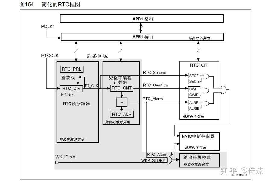
- RTC kernel is completely independent of APB1 interface, and software accesses RTC related registers through APB1 interface. However, the relevant registers are updated only on the rising edge of the RTC clock resynchronized by the RTC APB1 clock. Therefore, the software must wait until the register synchronization flag bit (RSF bit of RTC_CRL) is set to 1 by the hardware before reading.
2, HAL options
The board is STM32F103C8
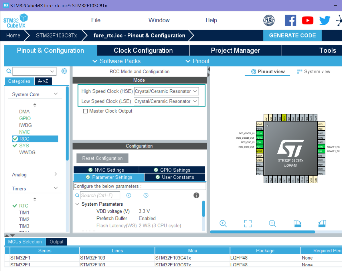
- RCC configuration. To enable the external low-speed clock, the SYS configuration does not need to be changed
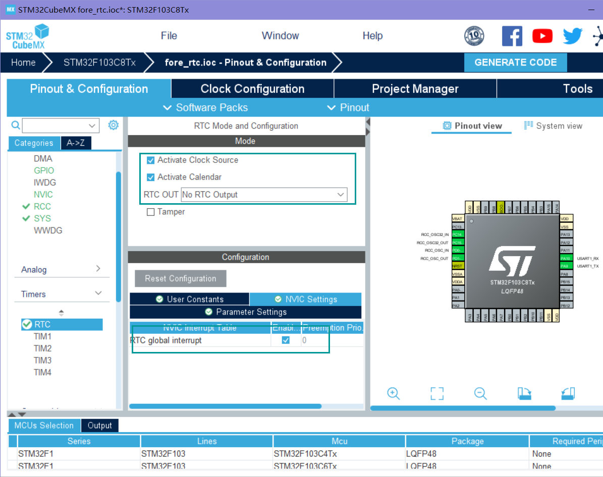
- The RTC module enables the clock source and calendar, and the RTC_ Select no rtc output for out, and add the following interrupt
- RTC_OUT is whether the output corrected second pulse clock on the tamper (PC13) pin is enabled.
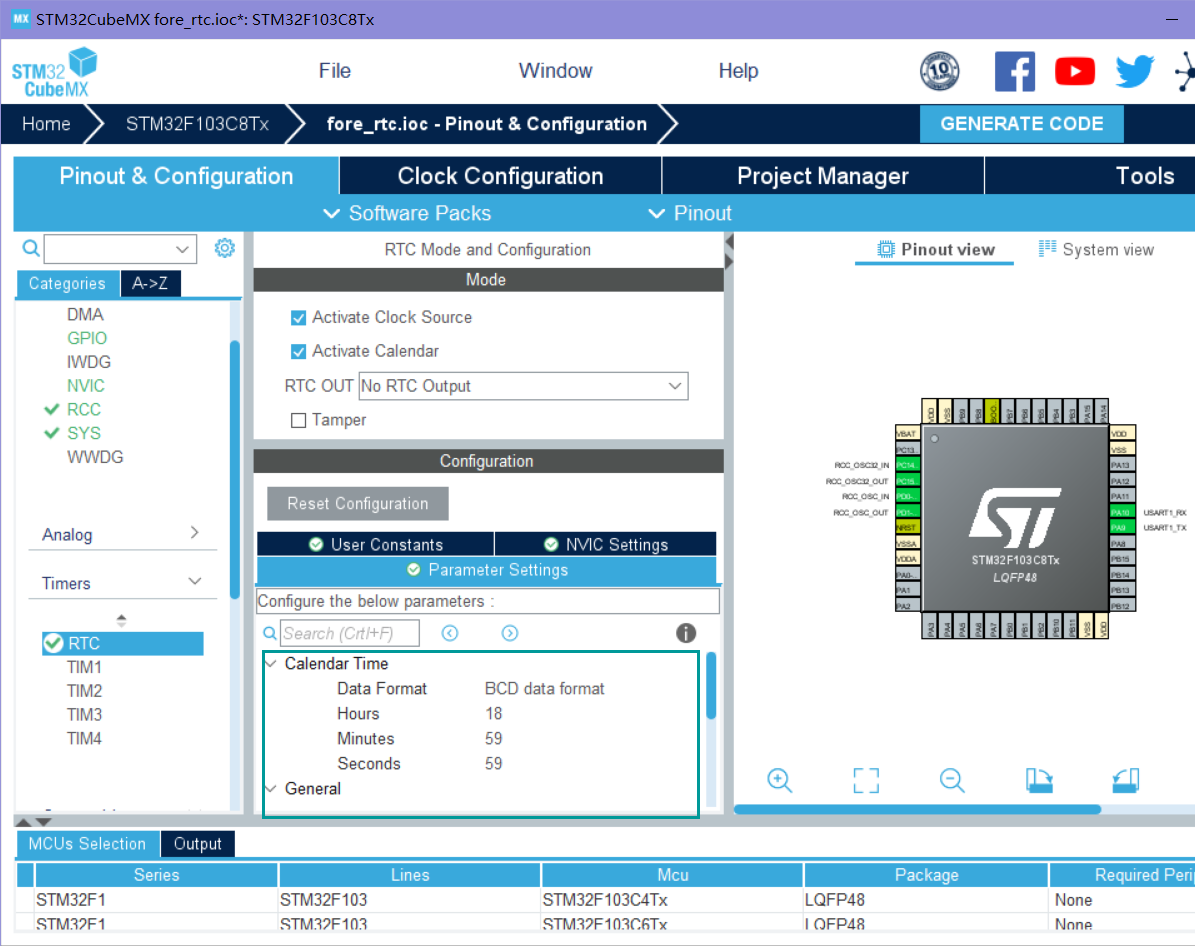
- In the parameter setting module, you can initialize the time or select the initialization time in the code
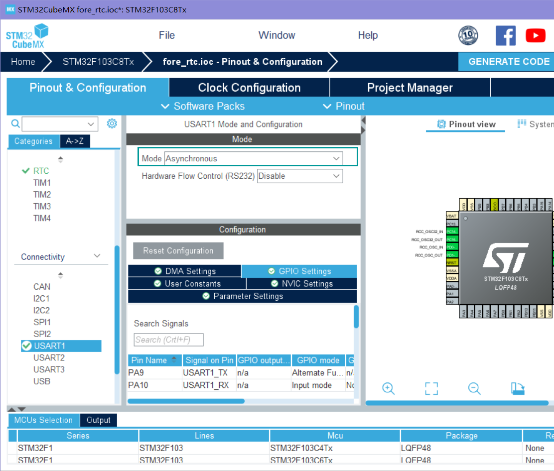
- To send information through the serial port, enable a usart1
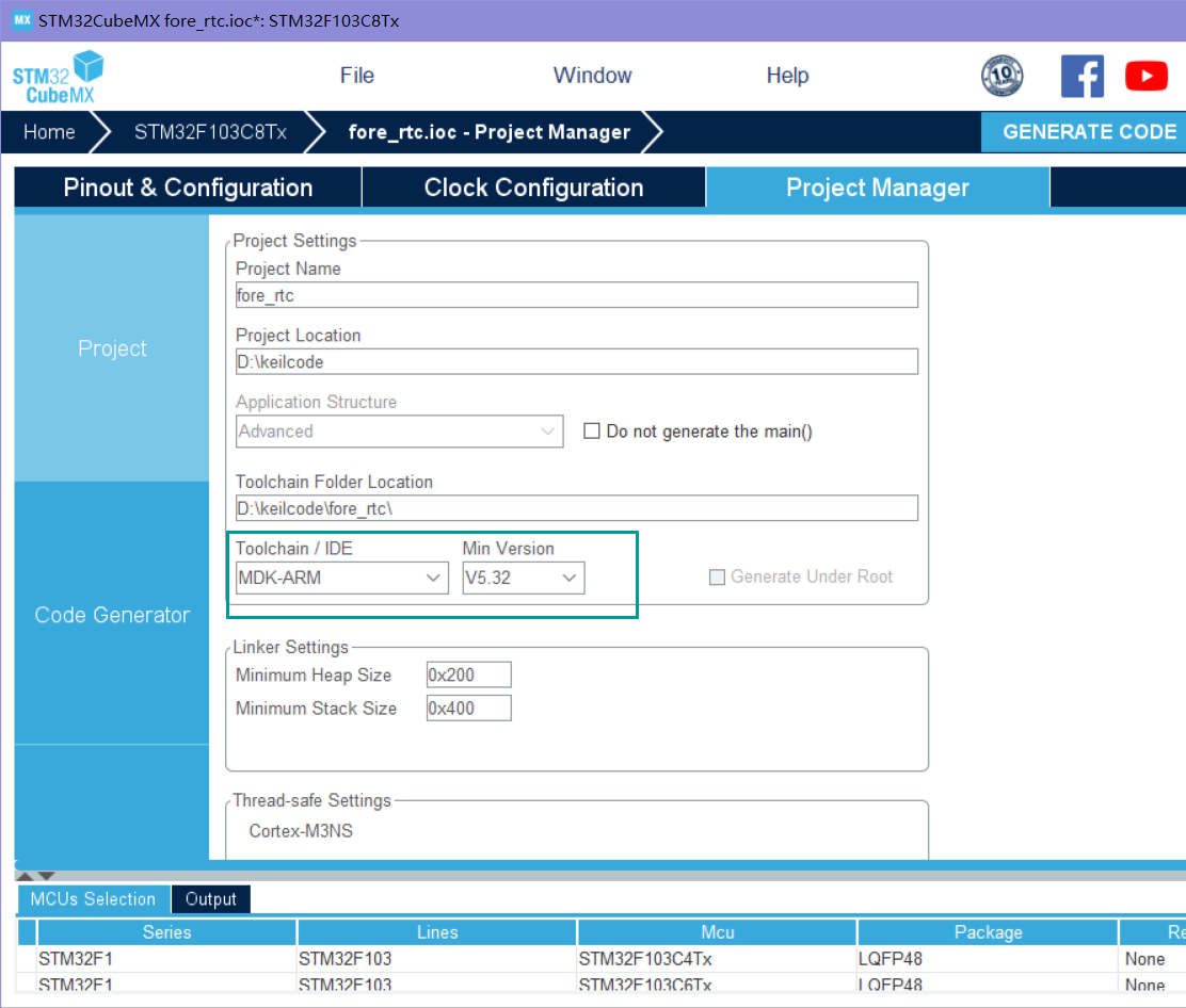
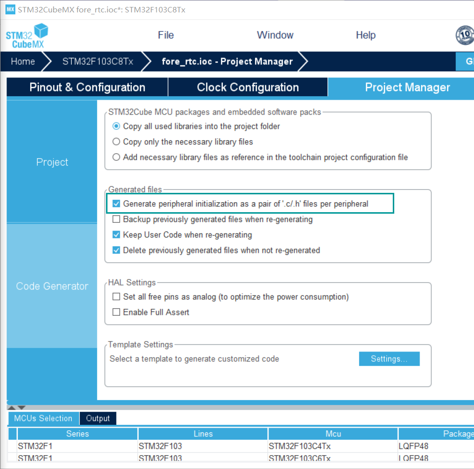
- The project management module changes the IDE to keil, and selects generate initialized. c code in the code generator
3, Code part
- Open keil and directly output the current time using the functions provided in hal library. The following is the main.c function code. Remember to select use microlib in target
/* USER CODE BEGIN Header */
/**
******************************************************************************
* @file : main.c
* @brief : Main program body
******************************************************************************
* @attention
*
* <h2><center>© Copyright (c) 2021 STMicroelectronics.
* All rights reserved.</center></h2>
*
* This software component is licensed by ST under BSD 3-Clause license,
* the "License"; You may not use this file except in compliance with the
* License. You may obtain a copy of the License at:
* opensource.org/licenses/BSD-3-Clause
*
******************************************************************************
*/
/* USER CODE END Header */
/* Includes ------------------------------------------------------------------*/
#include "main.h"
#include "rtc.h"
#include "usart.h"
#include "gpio.h"
#include "stdio.h"
int fputc(int ch,FILE *f){
uint8_t temp[1]={ch};
HAL_UART_Transmit(&huart1,temp,1,2);
return ch;
}
/* Private includes ----------------------------------------------------------*/
/* USER CODE BEGIN Includes */
/* USER CODE END Includes */
/* Private typedef -----------------------------------------------------------*/
/* USER CODE BEGIN PTD */
/* USER CODE END PTD */
/* Private define ------------------------------------------------------------*/
/* USER CODE BEGIN PD */
/* USER CODE END PD */
/* Private macro -------------------------------------------------------------*/
/* USER CODE BEGIN PM */
/* USER CODE END PM */
/* Private variables ---------------------------------------------------------*/
/* USER CODE BEGIN PV */
/* USER CODE END PV */
/* Private function prototypes -----------------------------------------------*/
void SystemClock_Config(void);
/* USER CODE BEGIN PFP */
/* USER CODE END PFP */
/* Private user code ---------------------------------------------------------*/
/* USER CODE BEGIN 0 */
/* USER CODE END 0 */
/**
* @brief The application entry point.
* @retval int
*/
int main(void)
{
/* USER CODE BEGIN 1 */
RTC_DateTypeDef GetData; //Get date structure
RTC_TimeTypeDef GetTime; //Get time structure
/* USER CODE END 1 */
/* MCU Configuration--------------------------------------------------------*/
/* Reset of all peripherals, Initializes the Flash interface and the Systick. */
HAL_Init();
/* USER CODE BEGIN Init */
/* USER CODE END Init */
/* Configure the system clock */
SystemClock_Config();
/* USER CODE BEGIN SysInit */
/* USER CODE END SysInit */
/* Initialize all configured peripherals */
MX_GPIO_Init();
MX_RTC_Init();
MX_USART1_UART_Init();
/* USER CODE BEGIN 2 */
/* USER CODE END 2 */
/* Infinite loop */
/* USER CODE BEGIN WHILE */
while (1)
{
/* USER CODE END WHILE */
/* Get the RTC current Time */
HAL_RTC_GetTime(&hrtc, &GetTime, RTC_FORMAT_BIN);//Get time
/* Get the RTC current Date */
HAL_RTC_GetDate(&hrtc, &GetData, RTC_FORMAT_BIN);//get date
/* Display date Format : yy/mm/dd */
printf("%02d/%02d/%02d\r\n",2000 + GetData.Year, GetData.Month, GetData.Date);
/* Display time Format : hh:mm:ss */
printf("%02d:%02d:%02d\r\n",GetTime.Hours, GetTime.Minutes, GetTime.Seconds);
printf("\r\n");
HAL_Delay(1000);
/* USER CODE BEGIN 3 */
}
/* USER CODE END 3 */
}
/**
* @brief System Clock Configuration
* @retval None
*/
void SystemClock_Config(void)
{
RCC_OscInitTypeDef RCC_OscInitStruct = {0};
RCC_ClkInitTypeDef RCC_ClkInitStruct = {0};
RCC_PeriphCLKInitTypeDef PeriphClkInit = {0};
/** Initializes the RCC Oscillators according to the specified parameters
* in the RCC_OscInitTypeDef structure.
*/
RCC_OscInitStruct.OscillatorType = RCC_OSCILLATORTYPE_HSE|RCC_OSCILLATORTYPE_LSE;
RCC_OscInitStruct.HSEState = RCC_HSE_ON;
RCC_OscInitStruct.HSEPredivValue = RCC_HSE_PREDIV_DIV1;
RCC_OscInitStruct.LSEState = RCC_LSE_ON;
RCC_OscInitStruct.HSIState = RCC_HSI_ON;
RCC_OscInitStruct.PLL.PLLState = RCC_PLL_ON;
RCC_OscInitStruct.PLL.PLLSource = RCC_PLLSOURCE_HSE;
RCC_OscInitStruct.PLL.PLLMUL = RCC_PLL_MUL9;
if (HAL_RCC_OscConfig(&RCC_OscInitStruct) != HAL_OK)
{
Error_Handler();
}
/** Initializes the CPU, AHB and APB buses clocks
*/
RCC_ClkInitStruct.ClockType = RCC_CLOCKTYPE_HCLK|RCC_CLOCKTYPE_SYSCLK
|RCC_CLOCKTYPE_PCLK1|RCC_CLOCKTYPE_PCLK2;
RCC_ClkInitStruct.SYSCLKSource = RCC_SYSCLKSOURCE_PLLCLK;
RCC_ClkInitStruct.AHBCLKDivider = RCC_SYSCLK_DIV1;
RCC_ClkInitStruct.APB1CLKDivider = RCC_HCLK_DIV2;
RCC_ClkInitStruct.APB2CLKDivider = RCC_HCLK_DIV1;
if (HAL_RCC_ClockConfig(&RCC_ClkInitStruct, FLASH_LATENCY_2) != HAL_OK)
{
Error_Handler();
}
PeriphClkInit.PeriphClockSelection = RCC_PERIPHCLK_RTC;
PeriphClkInit.RTCClockSelection = RCC_RTCCLKSOURCE_LSE;
if (HAL_RCCEx_PeriphCLKConfig(&PeriphClkInit) != HAL_OK)
{
Error_Handler();
}
}
/* USER CODE BEGIN 4 */
/* USER CODE END 4 */
/**
* @brief This function is executed in case of error occurrence.
* @retval None
*/
void Error_Handler(void)
{
/* USER CODE BEGIN Error_Handler_Debug */
/* User can add his own implementation to report the HAL error return state */
__disable_irq();
while (1)
{
}
/* USER CODE END Error_Handler_Debug */
}
#ifdef USE_FULL_ASSERT
/**
* @brief Reports the name of the source file and the source line number
* where the assert_param error has occurred.
* @param file: pointer to the source file name
* @param line: assert_param error line source number
* @retval None
*/
void assert_failed(uint8_t *file, uint32_t line)
{
/* USER CODE BEGIN 6 */
/* User can add his own implementation to report the file name and line number,
ex: printf("Wrong parameters value: file %s on line %d\r\n", file, line) */
/* USER CODE END 6 */
}
#endif /* USE_FULL_ASSERT */
/************************ (C) COPYRIGHT STMicroelectronics *****END OF FILE****/
- Output results
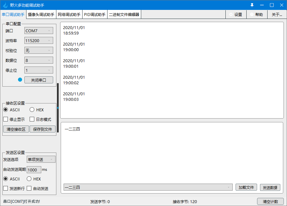
4, Summary
- It uses the built-in function of hal library, but it doesn't seem to understand the principle at all. It is measured by interrupt, and then it becomes the time to see after a series of processing. However, it seems that there is no time for detailed analysis of the principle recently. Write it in the memo and see if there is time to do it.
5, References
STM32 development – RTC details (Part I)
Real time clock
[STM32] HAL library STM32CubeMX tutorial XIII - RTC clock