preface
In this section, we will describe and introduce the general timer function of STM32, and also summarize STM32 (VI) and STM32 (VII)
---------------------—
catalogue
1. Introduction to general timer
2. Timer initialization function
3. PWM wave
---------------------—
I Introduction of timer
-------
1. What is a universal timer?
The general timer of STM32F1 is composed of a 16 bit free load counter (CNT) driven by a programmable prescaler (PSC). The general TIMx (2, 3, 4, 5) timer can be used to measure the pulse length of the input signal (input acquisition) or generate the output waveform (output comparison ^ PWM), etc
-------
2. Timer function
(1) 16 bit up-down} automatic load counter (TIMx_CNT)
(2) 16 bit programmable (real-time modifiable) prescaler (TIMx_PSC)
(3) 4 # independent channels (TIMx_CH1~4), which can be used as:
PWM, input capture, output comparison, single pulse mode output
__________________________
3. Conditions for interruption
A. update: counter overflow upward / downward, counter initialization (triggered by software or internal / external)
B. trigger events (counter start, stop, initialization or counting by internal / external trigger)
C. input capture
D. output comparison
E. support incremental (quadrature) encoder and Hall sensor circuits for positioning
F. trigger input as external clock or current management by cycle
--------
4. TIM clock source
Here, there are four clock sources of the timer:
(1) internal clock (CK_INT)
(2) external clock mode 1: external input pin (TIx)
(3) external clock mode 2: external trigger input (ETR)
(4) internal trigger input (ITRx): use timer A as prescaler of timer B (A provides clock for B)
--------
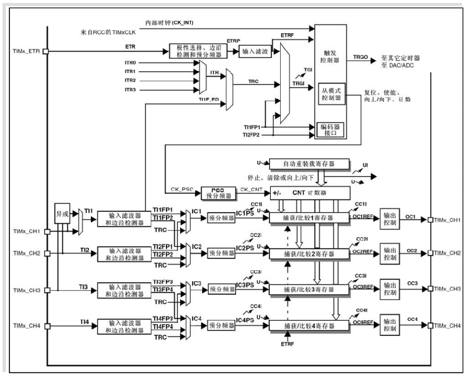
Note that TIMx_CNT} register, which is the counter of the timer. This register stores the count value of the current timer. Next, let's take a look at the following flow chart
---------------------
II Timer initialization function
_______________________________
Let's go through the general process of initialization
(1) No matter what peripheral it is, as long as it is used, we must enable the corresponding clock
(2) Initialization function (timer)
(3) Turn on the corresponding interrupt and configure the NVIC
(4) Enable timer
(5) Write the interrupt service function, which is used in the above interrupt
--------
First of all, we must define our function. Here, we define a function filled with two parameters
void TIM3_Int_Init(u16 arr,u16 psc);
arr: automatic reload value} psc: pre division frequency
Calculation method of clock:
When initializing with the SystenInit function, the clock frequencies are as follows:
SYSCLK = 72M
AHB clock = 72M
APB1 clock = 36M
Therefore, the frequency division coefficient of APB1 = AHB/APB1=2
Thus, CK can be obtained_ The clock frequency of int is 2*36M = 72M
The final frequency of the counter needs to be calculated by PSC prescaler
The generation time is mainly determined by TIMx_PSC and TIMx_ARR is determined by two register values, which is the cycle of the timer
Let's set timx first_ The value of arr register is 9999, that is, when TIMx_CNT is calculated from 0, which is just equal to the event generated at 9999, counting 10000 times in total. If the clock source cycle is 100us at this time, a timing cycle of just 1s can be obtained.
The next problem is to set TIMx_PSC register value makes CK_ The CNT output is a clock of 100us cycle (10000Hz). Input clock ck of Prescaler_ The PSC is 90MHz, so setting the prescaler value to (9000-1) is sufficient
--------
Next, we officially enter our configuration process
----------
1. Clock enable
void TIM3_Int_Init(u16 arr,u16 psc)
{
    TIM_TimeBaseInitTypeDef  TIM_TimeBaseStructure;
	NVIC_InitTypeDef NVIC_InitStructure;

	RCC_APB1PeriphClockCmd(RCC_APB1Periph_TIM3, ENABLE); //Clock enable
We have added several definitions to facilitate the following initialization functions. Similarly, we need to use the general timer 3 next, so we enable TIM3 (note which channel it is attached to)
--------
2. Initialize timer
TIM_TimeBaseStructure.TIM_Period = arr; //Sets the value of the auto reload register cycle of the load activity at the next update event

TIM_TimeBaseStructure.TIM_Prescaler =psc; //Sets the prescaled value used as the divisor of TIMx clock frequency

TIM_TimeBaseStructure.TIM_ClockDivision = TIM_CKD_DIV1; //Set clock division: TDTS = Tck_tim

TIM_TimeBaseStructure.TIM_CounterMode = TIM_CounterMode_Up;  //TIM up count mode

TIM_TimeBaseInit(TIM3, &TIM_TimeBaseStructure); //Initializes the time base unit of TIMx according to the specified parameters
We talked about our arr and psc earlier. Let's take a look at its counting mode
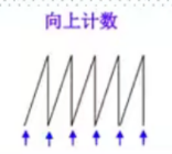
(1) Count up mode: the counter counts from 0 to the automatic loading value (arr), then generates a counter overflow event, and then starts counting from 0 again
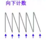
(2) Count down mode: the counter starts counting from arr to 0, then generates a counter overflow event, and then starts counting from 0 #
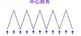
(3) Up / down counting mode: the counter starts counting from 0 to arr - 1, generates an overflow event, then starts counting from this value to 1, generates an overflow event, and then starts counting from 0
-------
3. Enable interrupt and configure NVIC
    TIM_ITConfig(TIM3,TIM_IT_Update,ENABLE ); //Enables the specified TIM3 interrupt and allows the update interrupt

	NVIC_InitStructure.NVIC_IRQChannel = TIM3_IRQn;  //TIM3 interrupt
	NVIC_InitStructure.NVIC_IRQChannelPreemptionPriority = 0;  //Preemption priority level 0
	NVIC_InitStructure.NVIC_IRQChannelSubPriority = 3;  //From priority level 3
	NVIC_InitStructure.NVIC_IRQChannelCmd = ENABLE; //IRQ channel enabled
	NVIC_Init(&NVIC_InitStructure);  //Initialize NVIC register
The following NVIC has been explained earlier. Let's take a look
TIM_ITConfig(TIM3,TIM_IT_Update,ENABLE );

static void TI3_Config(TIM_TypeDef* TIMx, uint16_t TIM_ICPolarity, uint16_t TIM_ICSelection,uint16_t TIM_ICFilter);
We can see that this function requires us to fill in three parameters: TIMx (channel), interrupt mode (we have selected a newer interrupt) and enable
___________________________________
4. Enable timer
TIM_Cmd(TIM3, ENABLE); //Enable TIMx
----------
5. Configure interrupt function
void TIM3_IRQHandler(void)   //TIM3 interrupt
{
	if (TIM_GetITStatus(TIM3, TIM_IT_Update) != RESET)  //Check whether the TIM3 update interrupt occurs
		{
		TIM_ClearITPendingBit(TIM3, TIM_IT_Update  );  //Clear TIMx update interrupt flag
		LED1=!LED1;
		}
}
Here we are just giving an example. Let's explain it:
We check our interrupt flag bit TIM_GetITStatus
If we detect that he is 1 (interrupt occurs), let the LED light change his state (on / off); Of course, we'd better clear our flag bit, or he'll get stuck in it_ ClearITPendingBit
We usually put him last
--------
In this way, our timer configuration is completed. Let's see how to use it
 int main(void)
 {

	delay_init();	    	 //Delay function initialization
	NVIC_PriorityGroupConfig(NVIC_PriorityGroup_2); //Set NVIC interrupt packet 2: 2-bit preemption priority and 2-bit response priority
	uart_init(115200);	 //The serial port is initialized to 115200
 	LED_Init();			     //LED port initialization
	TIM3_Int_Init(4999,7199);//The counting frequency of 10Khz is 500ms when counting to 5000
   	while(1)
	{
		LED0=!LED0;
		delay_ms(200);
	}


}
LED0 here is a comparison with LED1 to see if our timer is accurate
---------------------
III PWM wave
-------
1. What is PWM?
Pulse Width Modulation (PWM), the abbreviation of "Pulse Width Modulation", is a very effective technology to control analog circuits by using the digital output of microprocessor. It is widely used in many fields from measurement, communication to power control and conversion.
-------
2. How is PWM generated?
Speaking of this, we will explain it in the figure above (STM (VII))
---
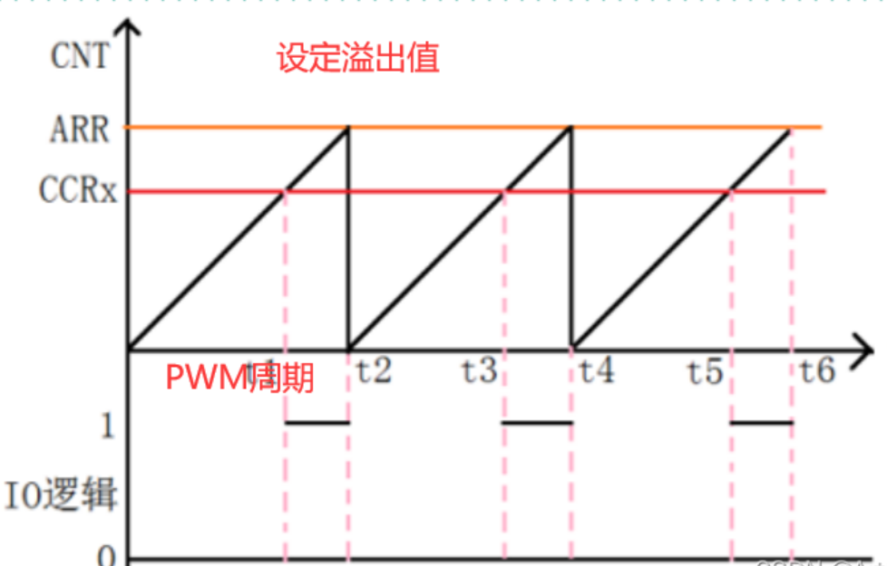
With the accumulation of the count value, it will reach the {orange line we set before. When it arrives, it will send an overflow signal, and then the count value will be cleared. Each cycle represents} a PWM cycle
One cycle of PWM:
The timer counts up from 0
When segment 0-t1, timer counter TIMx_CNT value is less than CCRx value, output low level
t1-t2 segment, timer counter TIMx_CNT value is greater than CCRx value, output high level
When timx_ When the CNT value reaches ARR, the timer overflows and counts up again Cycle this process
At this point, one PWM cycle is completed
The next question is how to produce high and low level changes in this cycle
——Flag value of duty cycle - (therefore, there is our red line, and CCRx determines the duty cycle). When CCRx is exceeded, the level changes from 0 to 1 (whether it changes to 0 or 1 depends on our configuration later. Here is an example)
------
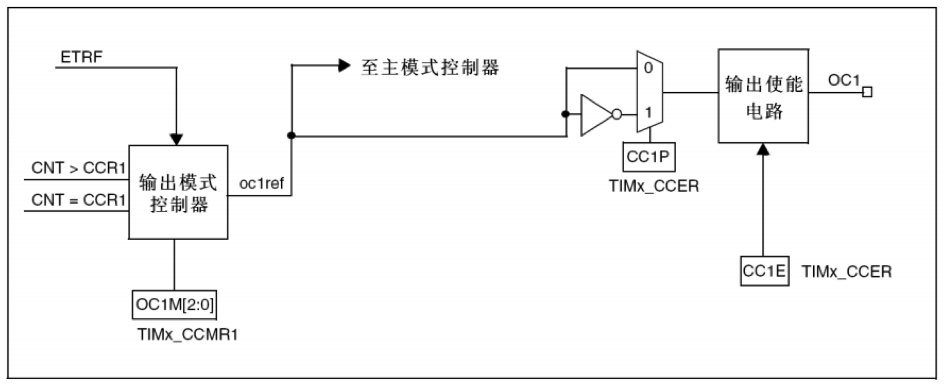
Here is his output flow
-----
3. PWM library function configuration
PWM configuration is based on TIM (timer) configuration
-----
First, define the initialization function. As before TIM, you need to configure arr and psc
void TIM3_PWM_Init(u16 arr,u16 psc)
-----
1. Enable timer (define structure)
void TIM3_PWM_Init(u16 arr,u16 psc)
{
	GPIO_InitTypeDef GPIO_InitStructure;
	TIM_TimeBaseInitTypeDef  TIM_TimeBaseStructure;
	TIM_OCInitTypeDef  TIM_OCInitStructure;


	RCC_APB1PeriphClockCmd(RCC_APB1Periph_TIM3, ENABLE);	//Enable timer 3 clock
 	RCC_APB2PeriphClockCmd(RCC_APB2Periph_GPIOB  | RCC_APB2Periph_AFIO, ENABLE);
    //Enable GPIO peripheral and AFIO multiplexing function module clock
We need lights to show the effect of our PWM, so we turn on GPIO and won't introduce it later
-----
   //Set this pin as the multiplexing output function to output the PWM pulse waveform of TIM3 CH2 	 GPIOB. five
	GPIO_InitStructure.GPIO_Pin = GPIO_Pin_5; //TIM_CH2
	GPIO_InitStructure.GPIO_Mode = GPIO_Mode_AF_PP;  //Multiplexed push-pull output
	GPIO_InitStructure.GPIO_Speed = GPIO_Speed_50MHz;
	GPIO_Init(GPIOB, &GPIO_InitStructure);//Initialize GPIO

   //Initialize TIM3
	TIM_TimeBaseStructure.TIM_Period = arr;
   //Sets the value of the auto reload register cycle of the load activity at the next update event
	TIM_TimeBaseStructure.TIM_Prescaler =psc; //Sets the prescaled value used as the divisor of TIMx clock frequency
	TIM_TimeBaseStructure.TIM_ClockDivision = 0; //Set clock division: TDTS = Tck_tim
	TIM_TimeBaseStructure.TIM_CounterMode = TIM_CounterMode_Up;  //TIM up count mode
	TIM_TimeBaseInit(TIM3, &TIM_TimeBaseStructure);
   //According to Tim_ The parameter specified in timebaseinitstruct initializes the time base unit of TIMx
-----
2. Configure PWM mode
	//Initialize TIM3 Channel2 PWM mode
	TIM_OCInitStructure.TIM_OCMode = TIM_OCMode_PWM2; //Select timer mode: TIM pulse width modulation mode 2
 	TIM_OCInitStructure.TIM_OutputState = TIM_OutputState_Enable; //Compare output enable
	TIM_OCInitStructure.TIM_OCPolarity = TIM_OCPolarity_High; //Output polarity: TIM output has high polarity
	TIM_OC2Init(TIM3, &TIM_OCInitStructure);  //Initialize the peripheral TIM3 OC2 according to the parameters specified by T
The polarity here means to set the effective high / low level, which requires us to cooperate with the above timer mode
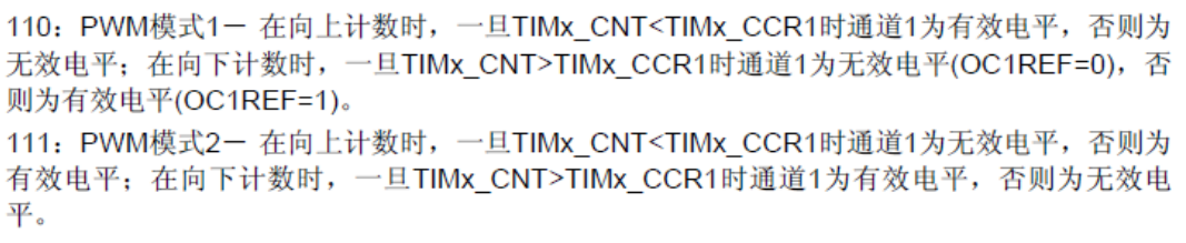
The PWM mode in STM32 only distinguishes when the active level is, but does not determine whether the high level is active or the low level is active, and which is the polarity setting
-----
3. Enable channel
Operation timx_ CC1P bit of CCER, modify channel polarity
void TIM_OC1NPolarityConfig(TIM_TypeDef* TIMx, uint16_t TIM_OCNPolarity);
	TIM_OC2PreloadConfig(TIM3, TIM_OCPreload_Enable);  //Enable TIM3 preload register on CCR2
	TIM_Cmd(TIM3, ENABLE);  //Enable TIM3
-------
After configuration, let's see how to use it
 int main(void)
 {
 	u16 led0pwmval=0;
	u8 dir=1;
	delay_init();	    	 //Delay function initialization
	NVIC_PriorityGroupConfig(NVIC_PriorityGroup_2);
    //Set NVIC interrupt packet 2: 2-bit preemption priority and 2-bit response priority
	uart_init(115200);	     //The serial port is initialized to 115200
 	LED_Init();			     //LED port initialization
 	TIM3_PWM_Init(899,0);	 //No frequency division. PWM frequency = 72000000/900=80Khz
   	while(1)
	{
 		delay_ms(10);
		if(dir1 == 1)// dir is originally assigned to 1
             led0pwmval++;
		else
             led0pwmval--;

 		if(led0pwmval>300)dir=0;
		if(led0pwmval==0)dir=1;
		TIM_SetCompare2(TIM3,led0pwmval);
	}
 }
-----
TIM_SetCompare2(TIM3,led0pwmval); / / change the comparison value tim3 - > CCR2 to adjust the duty cycle
Our comparison value is a variable, so it can be changed constantly
---------------------