Synchronized FIFO design and IP level verification
I. Preface
FIFO is the most common and basic topic when applying for IC front-end related positions. FIFO is often used for data caching, bit width conversion, asynchronous clock domain processing. With the rapid growth of chip size, flexible system verilog has become the basic skill of designers and validators. Starting with the simplified version of synchronous FIFO, this article is familiar with the basic skills of IP design and verification.
II. IP Design
FIFO, an IP core, is quite mature, so there are a lot of information on the Internet. The author believes that a better one in the appendix at the end of the article, need to understand the working principle of FIFO friends can take a closer look. Here is a brief introduction of the principle and structure of FIFO designed in this paper. The internal storage unit of FIFO is a common dual-port RAM. The essence of this IP is the external shielding and automatic management of read and write addresses. Avoiding full writing and empty reading is crucial. The two modules of FIFO top-level instantiated dual-port RAM and FIFO control are designed in this paper: the former is only used as memory unit to respond to read and write signals, while the latter generates read and write pointers and important empty and full indication signals according to read and write counters.
The code is as follows:
Storage module:


 1 `timescale 1ns/1ps
 2 module dpram
 3 #(parameter D_W=8,
 4             A_W=8)
 5 (
 6   input                   clk,
 7   input                   rst_n,
 8   //write ports
 9   input                   wr_en,
10   input       [D_W-1:0]   wr_data,
11   input       [A_W-1:0]   wr_addr,
12   //read ports
13   input                   rd_en,
14   input       [A_W-1:0]   rd_addr,
15   output reg  [D_W-1:0]   rd_data
16 );
17 //RAM
18 reg [D_W-1:0] memory [0:2**A_W-1];
19
20 //write operation
21 always@(posedge clk)begin
22   if(wr_en)begin
23     memory[wr_addr] <= wr_data;
24   end
25 end
26
27 //read operation
28 always@(posedge clk or negedge rst_n)begin
29   if(~rst_n)
30     rd_data <= 0;
31   else if(rd_en)begin
32     rd_data <= memory[rd_addr];
33   end
34   else if(rd_addr == 1)
35     rd_data <= memory[0];
36 end
37
38 endmodule
dpram
FIFO control module:
 1 `timescale 1ns/1ps
 2 module fifo_ctrl
 3 #(parameter A_W = 8,
 4   parameter [0:0] MODE = 0//0- standard read 1- first word fall through
 5 )
 6 (
 7   input clk,
 8   input rst_n,
 9
10   output [A_W-1:0] wr_addr,
11   output [A_W-1:0] rd_addr,
12
13   output empty,
14   output full,
15   input wr_en,
16   input rd_en
17 );
18 localparam MAX_CNT = 2**A_W;
19 localparam FD_W = A_W;
20
21 function [FD_W-1:0] abs;
22   input signed [FD_W-1:0] data;
23   begin
24     assign abs = data >= 0 ? data : -data;
25   end
26 endfunction
27
28 reg [A_W-1:0] wr_cnt;
29 wire add_wr_cnt,end_wr_cnt;
30 reg wr_flag;
31 reg [A_W-1:0] rd_cnt;
32 wire add_rd_cnt,end_rd_cnt;
33 reg rd_flag;
34 wire [A_W+1-1:0] wr_ptr,rd_ptr;
35
36 always@(posedge clk or negedge rst_n)begin
37   if(~rst_n)begin
38     wr_cnt <= 0;
39   end
40   else if(add_wr_cnt)begin
41     if(end_wr_cnt)
42       wr_cnt <= 0;
43     else
44       wr_cnt <= wr_cnt + 1'b1;
45   end
46 end
47
48 assign add_wr_cnt =  wr_en & ~full;
49 assign end_wr_cnt = add_wr_cnt && wr_cnt == MAX_CNT - 1;
50
51 always@(posedge clk or negedge rst_n)begin
52   if(~rst_n)begin
53     wr_flag <= 0;
54   end
55   else if(end_wr_cnt)begin
56     wr_flag <= ~wr_flag;
57   end
58 end
59
60 always@(posedge clk or negedge rst_n)begin
61   if(~rst_n)begin
62     rd_cnt <= 0;
63   end
64   else if(add_rd_cnt)begin
65     if(end_rd_cnt)
66       rd_cnt <= 0;
67     else
68       rd_cnt <= rd_cnt + 1'b1;
69   end
70 end
71
72 assign add_rd_cnt =  rd_en & ~empty;
73 assign end_rd_cnt = add_rd_cnt && rd_cnt ==  MAX_CNT - 1;
74
75 always@(posedge clk or negedge rst_n)begin
76   if(~rst_n)begin
77     rd_flag <= 0;
78   end
79   else if(end_rd_cnt)begin
80     rd_flag <= ~rd_flag;
81   end
82 end
83
84 assign wr_ptr = {wr_flag,wr_cnt};
85 assign rd_ptr = {rd_flag,rd_cnt};
86
87 assign wr_addr = wr_cnt;
88 assign rd_addr = rd_cnt + MODE;
89
90 assign empty = wr_ptr == rd_ptr;
91 assign full = (abs(wr_ptr[A_W-1:0] - rd_ptr[A_W-1:0]) < 1) && (wr_ptr[A_W] != rd_ptr[A_W]);
92
93 endmodule
fifo_ctrl
Synchronized FIFO Top Layer:
 1 `timescale 1ns/1ps
 2 module fifo_sync
 3 #(parameter D_W = 8,
 4             LOG_2_DEPTH = 8,//2^8 = 256
 5   parameter [0:0] MODE = 0
 6           )
 7 (
 8   input clk,
 9   input rst_n,
10
11   input wr_en,
12   input [D_W-1:0] wr_data,
13   input rd_en,
14   output [D_W-1:0] rd_data,
15   output wr_full,
16   output rd_empty
17 );
18 wire [LOG_2_DEPTH-1:0] wr_addr,rd_addr;
19
20 dpram #(.D_W(D_W),
21         .A_W(LOG_2_DEPTH))
22 dpram
23 (
24 .clk  (clk),
25 .rst_n (rst_n),
26 .wr_en  (wr_en),
27 .wr_data  (wr_data),
28 .wr_addr  (wr_addr),
29 .rd_en  (rd_en),
30 .rd_addr  (rd_addr),
31 .rd_data  (rd_data)
32 );
33
34 fifo_ctrl #(.A_W(LOG_2_DEPTH),
35             .MODE(MODE))
36 fifo_ctrl
37 (
38 .clk  (clk),
39 .rst_n  (rst_n),
40 .wr_addr (wr_addr),
41 .rd_addr (rd_addr),
42 .empty  (rd_empty),
43 .full  (wr_full),
44 .wr_en  (wr_en),
45 .rd_en  (rd_en)
46 );
47
48 endmodule
fifo_sync
In previous projects using FPGA, FIFO IP provided by the manufacturer often provides the "first word drop" mode, so this mode is also provided in this design, that is, the first written data is sent out before the read signal is valid. In addition, in order to improve the universality of the code, we try to use the parameter instead of the fixed value as the signal bit width in the design.
Third, SV builds testbench
Generally speaking, using verilog non-synthetic subset can also write testbench to verify the correctness of the design, but when DUT is more complex, it is not flexible enough. Synchronous FIFO is also designed to learn some skills of writing testbench with system verilog.
Firstly, the verification scheme is clear. Synchronized FIFO is nothing more than a read-write operation, as long as the data written can be read out every time, it is considered that the design is correct. We can read and write at any length and at any interval through the constrained random property of SV. It is difficult to compare data one by one when there are more data. Tesbench should also have a mechanism for automatically comparing data and counting errors.
Using OOP idea, three classes of descriptor transcation scorebord are designed, so it is an accessor that generates random read and write operations, and automatically compares the read and write data scoreboard according to the read and write operations of the accessor information. SV grammar is very flexible, each class can not only include function, but also support task, which brings convenience to sequential operation. It is also important to choose the right data type. Because the length of the data to be written is not fixed, it is appropriate to use dynamic arrays. The increasing reading data information, placed in the queue will be more efficient. Whether FIFO chooses "acronym drop" mode or not has a direct impact on the timing of reading operation. In testbench, macro definition is used to compile condition parameters and read acquisition logic.
The code is as follows:
  1 `timescale 1ns/1ps
  2 `define VERDI
  3 //`define FW
  4
  5 module testbench();
  6
  7   parameter CYC = 20,
  8             RST_TIM = 2;
  9   parameter D_W = 8,
 10             LOG_2_DEPTH = 8;
 11
 12   `ifdef FW
 13     parameter [0:0] MODE = 1'b1;//1'b1 1'b0
 14   `else
 15     parameter [0:0] MODE = 1'b0;
 16   `endif
 17   parameter MAX_LEN = 2**LOG_2_DEPTH;
 18
 19   typedef int unsigned uint32;
 20   typedef enum {true,false} status_e;
 21
 22   bit clk,rst_n;
 23   bit wr_en;
 24   bit [D_W-1:0] wr_data;
 25   bit rd_en;
 26   logic [D_W-1:0] rd_data;
 27   logic wr_full;
 28   logic rd_empty;
 29   reg rd_en_t;
 30
 31   `ifdef VERDI
 32   initial begin
 33     $fsdbDumpfile("wave.fsdb");
 34     $fsdbDumpvars("+all");
 35   end
 36   `endif
 37
 38   initial begin
 39     clk = 1;
 40     forever #(CYC/2.0) clk= ~clk;
 41   end
 42
 43   initial begin
 44     rst_n = 1;
 45     #1;
 46     rst_n = 0;
 47     #(RST_TIM*CYC) rst_n = 1;
 48   end
 49
 50   class Descriptor;
 51     rand bit [16-1:0] len_w,len_r,interval;
 52
 53     constraint c {
 54                    len_w inside {[1:20]};
 55                    len_r inside {[0:20]};
 56                    interval inside {[2:6]};
 57                   }
 58     function new;
 59       $display("Created a object");
 60     endfunction
 61   endclass:Descriptor
 62
 63   class Transcation;
 64     bit [D_W-1:0] data_packet[];
 65     static uint32 q_len[$];
 66     static uint32 q_rd_data[$];
 67     uint32 q_ref_data[$];
 68
 69     Descriptor dp;
 70
 71     function new();
 72       dp = new();
 73       assert(dp.randomize());
 74       q_len.push_back(dp.len_w);
 75     endfunction
 76
 77     extern task wri_oper;
 78     extern task rd_oper;
 79     extern task wr_rd_operation;
 80     extern function void ref_gen(ref uint32 q_ref_data[$]);
 81
 82   endclass:Transcation
 83
 84   task Transcation::wri_oper;
 85     uint32 wr_num;
 86     $display("Write:%d",$size(tr.data_packet));
 87     @(posedge clk);
 88     #1;
 89     while(wr_num < dp.len_w)begin
 90       if(~wr_full)begin
 91         wr_en = 1;
 92         wr_data = tr.data_packet[wr_num];
 93         wr_num++;
 94       end
 95       else begin
 96         wr_en = 0;
 97         wr_data = tr.data_packet[wr_num];
 98       end
 99       #(CYC*1);
100     end
101     wr_en = 0;
102   endtask
103
104   task Transcation::rd_oper;
105     uint32 rd_num;
106     $display("Read: %d",dp.len_r);
107     @(posedge clk);
108     #1;
109     #(dp.interval*CYC);
110     while(rd_num < dp.len_r)begin
111       if(~rd_empty)begin
112         rd_en = 1;
113         rd_num++;
114       end
115       else
116         rd_en = 0;
117       #(CYC*1);
118     end
119     rd_en = 0;
120   endtask
121
122   task Transcation::wr_rd_operation;
123     tr.data_packet = new[dp.len_w];
124     $display("len_w = %d, len_r = %d, inverval = %d",dp.len_w,dp.len_r,dp.interval);
125     foreach(tr.data_packet[i])begin
126       tr.data_packet[i] = i+1;
127       //$display(tr.data_packet[i]);
128     end
129     fork
130       wri_oper;
131       rd_oper;
132     join
133   endtask
134
135   function void Transcation::ref_gen(ref uint32 q_ref_data[$]);
136     integer j;
137     foreach(q_len[i])begin
138       for(j=0;j<q_len[i];j++)begin
139         q_ref_data = {q_ref_data,j+1};
140       end
141     end
142   endfunction
143
144   class Scoreboard;
145     uint32 total_num,error_num = 0;
146
147     function compare(ref uint32 q_data[$],ref uint32 q_ref[$]);
148       uint32 comp_num;
149       uint32 i;
150       uint32 data_len,ref_len;
151       status_e status;
152       data_len = $size(q_data);
153       ref_len = $size(q_ref);
154       $display("The lengths of q_data and q_ref are %d,%d",$size(q_data),$size(q_ref));
155       if(data_len >= ref_len)
156         comp_num = ref_len;
157       else
158         comp_num = data_len;
159       total_num = comp_num;
160       for(i=0;i<comp_num;i++)begin
161         if(q_data[i] != q_ref[i])begin
162           error_num++;
163           $display("The %dth data is different between the two!",i);
164           status = false;
165           return status;
166         end
167       end
168       status = true;
169       return status;
170     endfunction
171   endclass
172
173    //Descriptor dp;
174    Transcation tr;
175    Scoreboard sb;
176
177   //main
178   initial begin
179     //int status;
180     status_e status;
181     wr_en = 0;
182     rd_en = 0;
183     wr_data = 0;
184     #1;
185     #(2*CYC);
186     repeat(2)begin
187       tr = new();
188       tr.wr_rd_operation;
189       #(50*CYC);
190     end
191     #20;
192     tr.ref_gen(tr.q_ref_data);
193
194     //soreboard
195     sb = new();
196     status = sb.compare(tr.q_rd_data,tr.q_ref_data);
197     if(status == true)
198       $display("Simulation success!");
199     else
200       $display("Simulation filure!");
201     $stop;
202   end
203
204   //save readed data
205   initial begin
206     forever begin
207       @(posedge clk);
208         `ifdef FW
209           if(rd_en)
210         `else
211           if(rd_en_t)
212         `endif
213             tr.q_rd_data = {tr.q_rd_data,rd_data};
214     end
215   end
216
217   always@(posedge clk)begin
218     rd_en_t <= rd_en;
219   end
220
221   fifo_sync
222 #(.D_W(D_W),
223   .LOG_2_DEPTH(8),//256
224   .MODE(MODE)
225   )uut
226   (
227   .clk  (clk),
228   .rst_n  (rst_n),
229   .wr_en  (wr_en),
230   .wr_data  (wr_data),
231   .rd_en  (rd_en),
232   .rd_data  (rd_data),
233   .wr_full  (wr_full),
234   .rd_empty  (rd_empty)
235   );
236
237 endmodule:testbench
testbench.sv
IV. Use of VCS+Verdi Tools
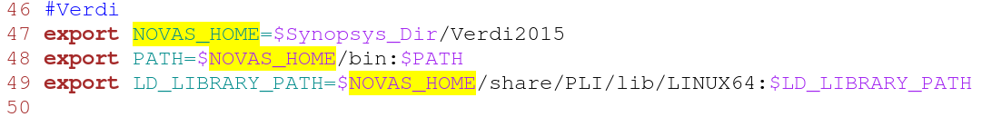
It has to be said that most EDA tools are not as friendly as the development tools in IT industry, and it takes a lot of effort to use them. VCS has its own GUI debug tool, but it is not powerful enough. Here we use Verdi to debug. In the SV code in the previous section, there is a section of fsdb code that is specifically designed to generate Verdi waveform files. Since SV itself does not have these two system function s, it is necessary to specify two library file paths when using SV. The author directly defines an alias: (bash shell) for lengthy commands and options.
alias vcs_verdi="vcs -full64 -sverilog -debug_all -P ${NOVAS_HOME}/share/PLI/VCS/linux64/novas.tab ${NOVAS_HOME}/share/PLI/VCS/linux64/pli.a +define+DUMPFSDB"
.bashrc file:
This path name seems to have to be NOVAS_HOME, otherwise it will make an error, which is also a pit. The first step of code compilation is accomplished by using the above instructions, followed by the execution of the simulation program and the invocation of the Verdi GUI interface to observe the waveform. The order is:
./simv
verdi -sv -f filename -ssf wave.fsdb
The waveform file specified in testbench will be generated after simulation. The verdi interface is opened after the third step command is executed.
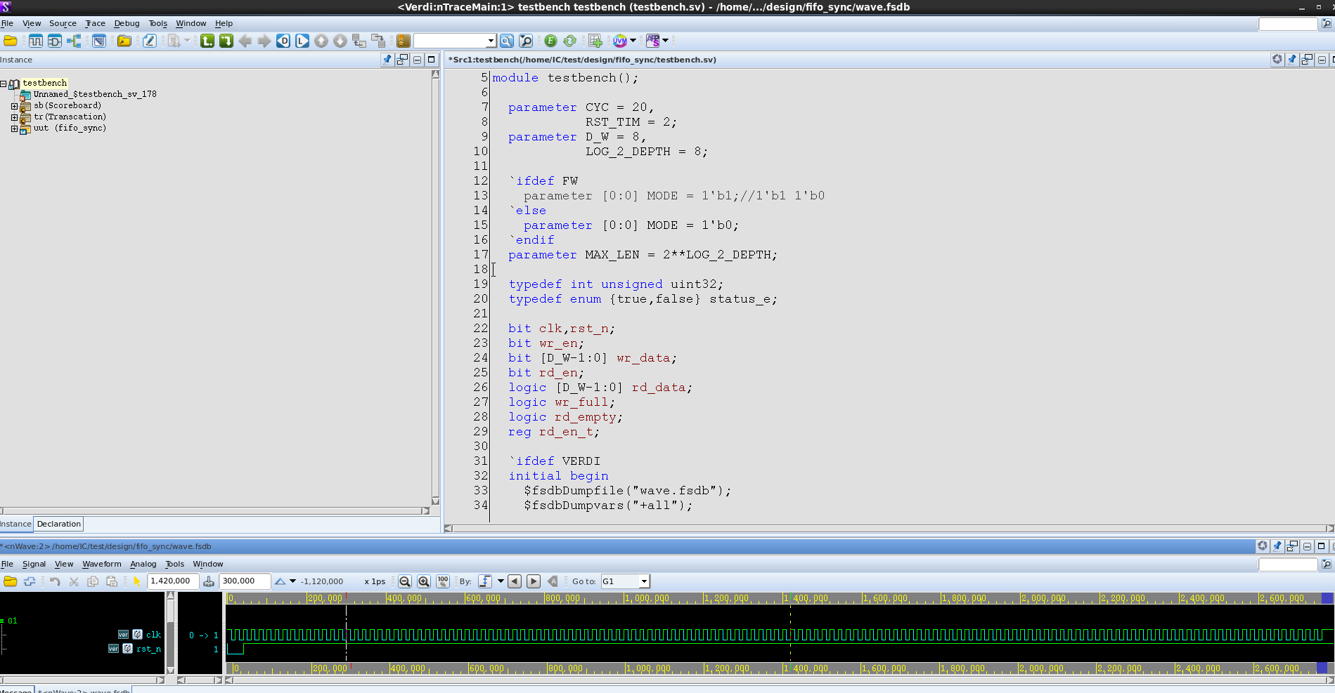
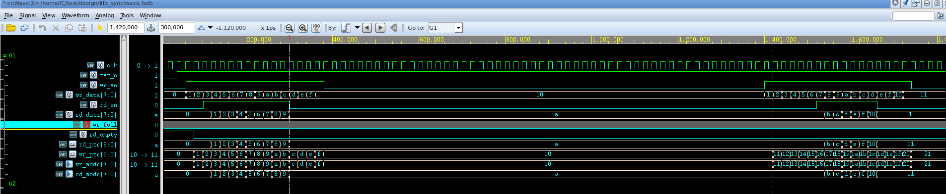
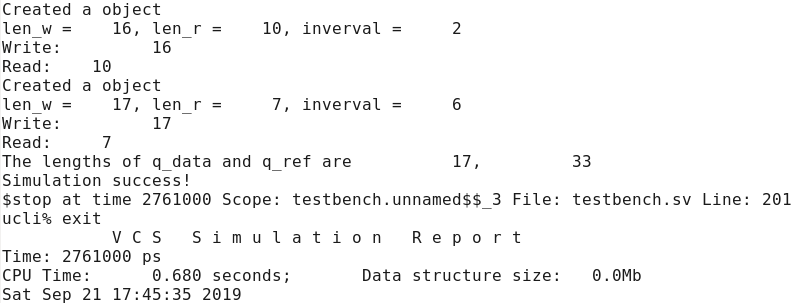
Through waveform and Log after simulation, we can see that the simulation is passed, and there are no errors in reading and writing FIFO.
Here are some basic techniques for using verdi.
Observe the specified signal waveform: Select the variable in the code and add it to the waveform window by ctrl+w.
Save the waveform configuration file: In the waveform interface, press shift+s to save the. rc file.
Retrieve the stored configuration file: click r, select the stored. rc file and open it.
For the first time, the author uses OOP idea to build testbench with SV, and also uses VCS+Verdi tool chain to simulate and debug. Despite the simplicity of design validation, it still stuck many times. Asynchronous FIFO design and reusable testbench based on UVM will be tried later.
~~~~~~~~~~~~~~~~~~~~~~~~~~~~~~~~~~~~~~~~~~~~~~~~~~~~~~~~~~~~~~~~~~~~~~~~~~~~~~~~~~~~~~~~~~~~~~~~~~~~~~~~~~~~~~~~~~~~~~~~~
appendix
1 [Image and Text] Synchronized FIFO-Baidu Library https://wenku.baidu.com/view/620e3934a32d7375a4178037.html
2. EDA under linux - VCS and Verdi simulation - blog of moon9999 - CSDN blog https://blog.csdn.net/moon9999/article/details/76615869
Keywords:
Verilog
shell
Linux
Added by ianhull on Sat, 21 Sep 2019 15:43:49 +0300