4.3 verify the implementation effect of OpenMIPS
4.3.1 implementation of instruction memory ROM
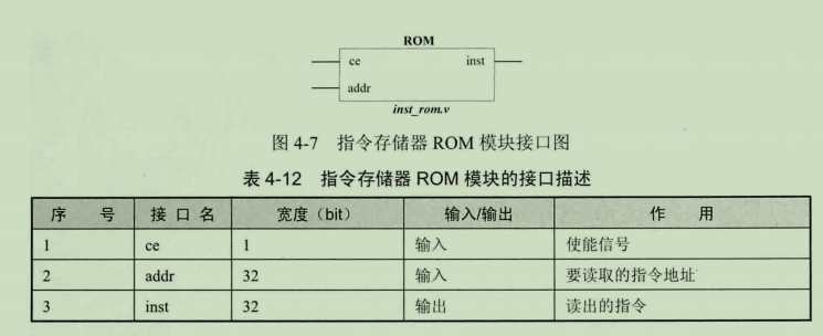
In this section, we verify whether OpenMIPS is implemented correctly, including whether the pipeline and ori instructions are implemented correctly. The instruction memory ROM is read-only, and the interface is shown in the figure:
`include "defines.v"

module inst_rom(

//	input	wire										clk,
	input wire                    ce,
	input wire[`InstAddrBus]			addr,
	output reg[`InstBus]					inst

);

	reg[`InstBus]  inst_mem[0:`InstMemNum-1];

	initial $readmemh ( "inst_rom.data", inst_mem );

	always @ (*) begin
		if (ce == `ChipDisable) begin
			inst <= `ZeroWord;
	  end else begin
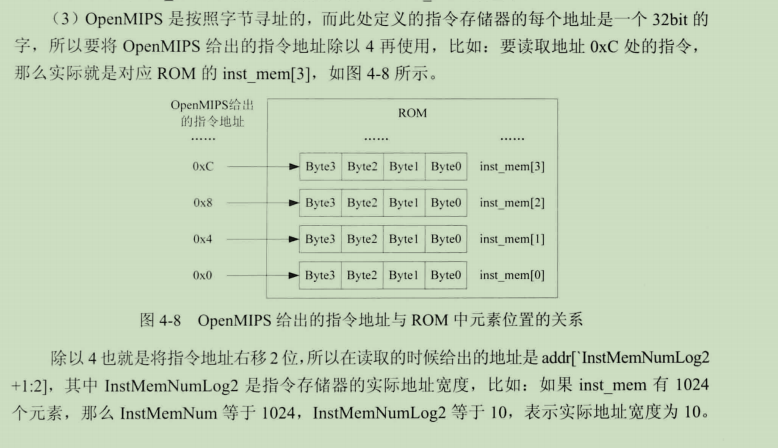
		  inst <= inst_mem[addr[`InstMemNumLog2+1:2]];
		end
	end

endmodule


4.3.2 realization of minimum SOPC
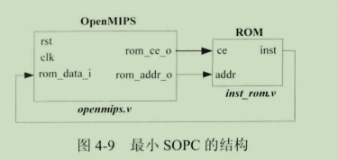
In order to verify, a SOPC needs to be established, in which only openmips and instruction memory ROM are available, so it is a minimum SOPC. Openmips reads instructions from the instruction memory, and the instructions enter openmips and start execution. The structure of the minimum SOPC is shown in the figure:
`include "defines.v"

module openmips_min_sopc(

	input	wire										clk,
	input wire										rst

);

  wire[`InstAddrBus] inst_addr;
  wire[`InstBus] inst;
  wire rom_ce;


 openmips openmips0(
		.clk(clk),
		.rst(rst),

		.rom_addr_o(inst_addr),
		.rom_data_i(inst),
		.rom_ce_o(rom_ce)

	);

	inst_rom inst_rom0(
		.addr(inst_addr),
		.inst(inst),
		.ce(rom_ce)
	);


endmodule

4.3.3 preparation of test procedures
We write a test program and store it in the instruction memory ROM, so that when the minimum SOPC starts running, our program will be taken out of the ROM and sent to the OpenMIPS processor for execution.
The test program has four instructions, all of which are ori instructions
	.org 0x0
.global _start
   .set noat
_start:
   ori $1,$0,0x1100        # $1 = $0 | 0x1100 = 0x1100
   ori $2,$0,0x0020        # $2 = $0 | 0x0020 = 0x0020
   ori $3,$0,0xff00        # $3 = $0 | 0xff00 = 0xff00
   ori $4,$0,0xffff        # $4 = $0 | 0xffff = 0xffff
- The first instruction performs logical or operation with register $0 after zero extension of 0x1100, and the result is saved in register $1
- The second instruction performs a logical or operation with register $0 after zero extension of 0x0020, and the result is saved in register $2
- The first instruction performs a logical or operation with register $0 after zero extension of 0xff00, and the result is saved in register $3
- The first instruction performs a logical or operation with register $0 after zero extension of 0xffff, and the result is saved in register $4
Definition of zero extension: Zero extension is very simple. You only need to fill the high-end bytes of large digit operands with zeros.
For details, please refer to the following articles: https://blog.csdn.net/yjk13703623757/article/details/78084491
4.3.4 create Test Bench file
Give the clock signal and reset signal required for the minimum SOPC operation. The code is as follows:
`include "defines.v"
`timescale 1ns/1ps

module openmips_min_sopc_tb();

  reg     CLOCK_50;
  reg     rst;


  initial begin
    CLOCK_50 = 1'b0;
    forever #10 CLOCK_50 = ~CLOCK_50;
  end

  initial begin
    rst = `RstEnable;
    #195 rst= `RstDisable;
    #1000 $stop;
  end

  openmips_min_sopc openmips_min_sopc0(
		.clk(CLOCK_50),
		.rst(rst)
	);

endmodule
4.3.5 detection effect
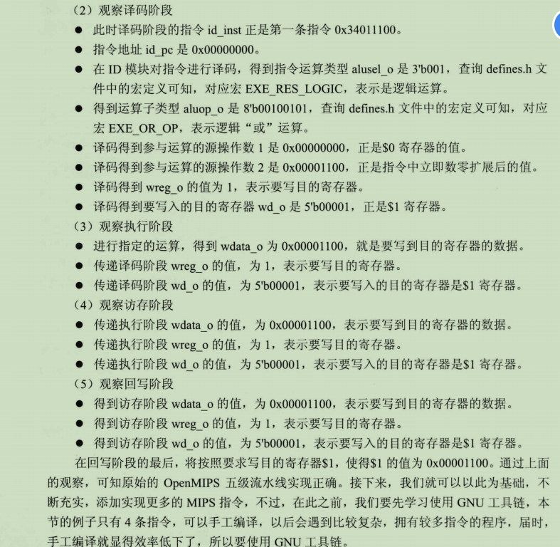
I can't understand the part of the book here. I personally use Vivado to run and test, and a circuit diagram will appear. I took some screenshots from the book, and the result of my own test was the same circuit diagram

