**
preface
**
Recently, I participated in the Dachuang project. The topic involves computer vision. My sister sent a blog link to correct the image, so I plan to use this topic to get started with OpenCV.
Analyze problems
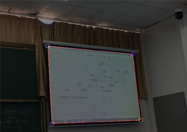
The PPT area in the photo is always inclined along the X, y and Z axes (as shown in the figure below). To flip the photo to the parallel position, perspective transformation needs to be carried out, and perspective transformation needs the coordinates before and after the transformation of the same pixel. It can be imagined that the coordinates of the four corners of the rectangular area can be extracted as the coordinates before the transformation, and the transformed coordinates can be set as the four corners of the photo. After projection transformation, the rectangular area will flip and fill the image.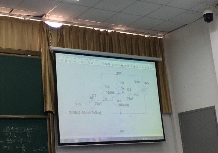
Therefore, the problem we want to solve is to extract the four corners of the rectangle and carry out perspective transformation.
Extract rectangular corner coordinates
The detection of rectangle is mainly to extract the edge. The brightness of PPT display part is usually higher than the surrounding environment. We can threshold the picture and clearly separate the PPT part from the surrounding environment, which is very helpful for the edge detection in the back.
Detecting rectangle and extracting coordinates requires image preprocessing, edge detection, contour extraction, convex hull detection and corner detection.
Pretreatment
Because the pixels of the photos taken by the mobile phone may be very high, in order to speed up the processing speed, we first reduce the picture, which is reduced by 4 times.
pyrDown(srcPic,      shrinkedPic);        //Reduce size and speed up operation
pyrDown(shrinkedPic, shrinkedPic);
Convert to grayscale
cvtColor(shrinkedPic, greyPic, COLOR_BGR2GRAY); //Convert to grayscale image
median filtering
medianBlur(greyPic, greyPic, 7); //median filtering
Convert to binary picture
threshold(greyPic, binPic, 80, 255, THRESH_BINARY); //Thresholding to binary image
At this time, the picture has become like this: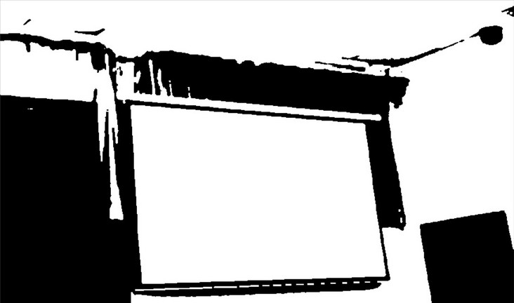
It can be seen that the PPT part has been separated from the environment.
Edge detection and contour processing
Canny edge detection
Canny(binPic, cannyPic, cannyThr, cannyThr*FACTOR); //Canny edge detection
Here cannyThr = 200, FACTOR = 2.5
Perhaps because the edge features are too obvious, the effect of the coefficient in the range of 100-600 (the specific number may be different, but the range is very large anyway) is almost the same.
Extract contour
vector<vector<Point>> contours;    //Storage profile
vector<Vec4i> hierarchy;

findContours(cannyPic, contours, hierarchy, RETR_CCOMP, CHAIN_APPROX_SIMPLE);    //Get profile
The prototype of findContour function is as follows:
CV_EXPORTS_W void findContours( InputOutputArray image, OutputArrayOfArrays contours,
                             OutputArray hierarchy, int mode,
                            int method, Point offset = Point());
The detected contours are stored in contours, and each contour is saved as a vector
hierarchy is an optional output vector, including the topological information of the image. You can choose not to use it here.
We can repeatedly call the drawContours function to draw the outline
linePic = Mat::zeros(cannyPic.rows, cannyPic.cols, CV_8UC3);
for (int index = 0; index < contours.size(); index++){
        drawContours(linePic, contours, index, Scalar(rand() & 255, rand() & 255, rand() & 255), 1, 8/*, hierarchy*/);
}
drawContours function prototype:
CV_EXPORTS_W void drawContours( InputOutputArray image, InputArrayOfArrays contours,
                            int contourIdx, const Scalar& color,
                            int thickness = 1, int lineType = LINE_8,
                            InputArray hierarchy = noArray(),
                            int maxLevel = INT_MAX, Point offset = Point() );
The function is to draw the contour of contourIdx in contours into the image with color color. Thickness is the thickness of the line. When contourIdx is a negative number, draw all contours
It should be noted here that space should be allocated for the output matrix in advance before drawing the contour, otherwise the following errors will occur
OpenCV(3.4.1) Error: Assertion failed (size.width>0 && size.height>0) in cv::imshow, file C:\build\master_winpack-build-win64-vc15\opencv\modules\highgui\src\window.cpp, line 356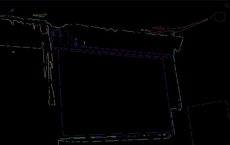
Extract the contour with the largest area and surround it with polygons
It can be seen from the above contour map that the rectangle of PPT has become the main part of the picture. The next idea is to extract the contour with the largest area to obtain the rectangular contour.
vector<vector<Point>> polyContours(contours.size());
int maxArea = 0;
for (int index = 0; index < contours.size(); index++){
        if (contourArea(contours[index]) > contourArea(contours[maxArea]))
            maxArea = index;
        approxPolyDP(contours[index], polyContours[index], 10, true);
    }
contourArea is used to calculate the area of the contour
The function of approxPolyDP is to surround the contour with polygons, which can get a strict rectangle and help to find corners
Draw a rectangle, and also pay attention to allocating space for Mat in advance
Mat polyPic = Mat::zeros(shrinkedPic.size(), CV_8UC3);
drawContours(polyPic, polyContours, maxArea, Scalar(0,0,255/*rand() & 255, rand() & 255, rand() & 255*/), 2);
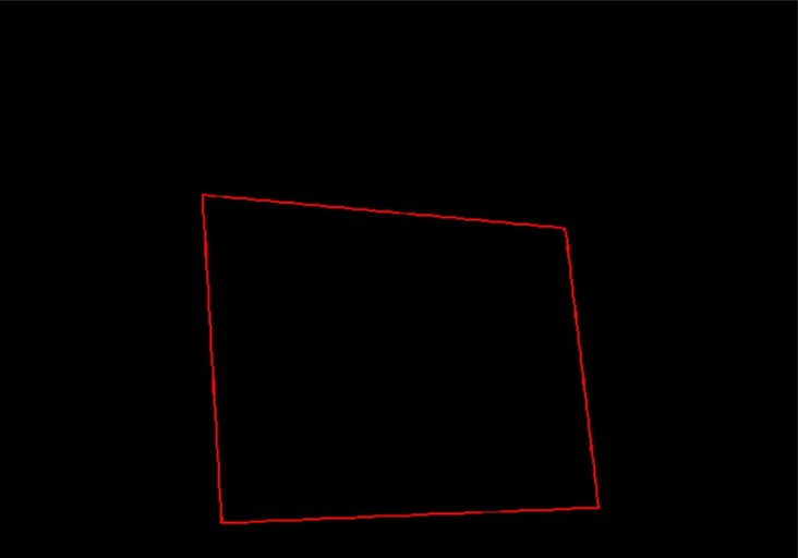
As shown in the figure, we only need to extract the coordinates of the four corners
Finding convex hull
vector<int>  hull;
convexHull(polyContours[maxArea], hull, false);    //Detects the convex hull of the profile
convexHull function prototype
CV_EXPORTS_W void convexHull( InputArray points, OutputArray hull,
                            bool clockwise = false, bool returnPoints = true );
Hull is the output parameter. Clockwise determines the clockwise and counterclockwise direction of the convex hull. When returnPoints is true, it returns each point of the convex hull. Otherwise, it returns the index of each point
Hull can be of type vector. In this case, the index of the convex hull point in the original figure is returned
We can add points and polygons to the original image to see the effect
for (int i = 0; i < hull.size(); ++i){
        circle(polyPic, polyContours[maxArea][i], 10, Scalar(rand() & 255, rand() & 255, rand() & 255), 3);
    }
addWeighted(polyPic, 0.5, shrinkedPic, 0.5, 0, shrinkedPic);
Now that we have accurately obtained the required points, we will use these points for coordinate mapping.
Projection transformation
Projection transformation requires one-to-one correspondence between the coordinates of pixels in the two coordinate systems. Although we already have four coordinates, we have not distinguished their positions.
Create two new arrays
Point2f srcPoints[4], dstPoints[4];
dstPoints[0] = Point2f(0, 0);
dstPoints[1] = Point2f(srcPic.cols, 0);
dstPoints[2] = Point2f(srcPic.cols, srcPic.rows);
dstPoints[3] = Point2f(0, srcPic.rows);
dstPoints stores the coordinates of each point after transformation, which are upper left, upper right, lower right and lower left
srcPoints stores the coordinates of the four corners obtained above
The four points obtained are processed below
for (int i = 0; i < 4; i++){
    polyContours[maxArea][i] = Point2f(polyContours[maxArea][i].x * 4, polyContours[maxArea][i].y * 4); //Restore coordinates to original drawing
}
        //Sort the four points and divide them into upper left, upper right, upper right, lower right and lower left
bool sorted = false;
int n = 4;
while (!sorted){
    for (int i = 1; i < n; i++){
    sorted = true;
        if (polyContours[maxArea][i-1].x > polyContours[maxArea][i].x){
            swap(polyContours[maxArea][i-1], polyContours[maxArea][i]);
            sorted = false;
        }
    }
    n--;
}
if (polyContours[maxArea][0].y < polyContours[maxArea][1].y){
    srcPoints[0] = polyContours[maxArea][0];
    srcPoints[3] = polyContours[maxArea][1];
}
else{
    srcPoints[0] = polyContours[maxArea][1];
    srcPoints[3] = polyContours[maxArea][0];
}

if (polyContours[maxArea][9].y < polyContours[maxArea][10].y){
    srcPoints[1] = polyContours[maxArea][2];
    srcPoints[2] = polyContours[maxArea][3];
}
else{
    srcPoints[1] = polyContours[maxArea][3];
    srcPoints[2] = polyContours[maxArea][2];
}
That is, first bubble sort the x coordinates of the four points, divide the left and right, and then divide the up and down according to the comparison of the y values of the two pairs of coordinates
(the author tried to get the position information through the clockwise and counterclockwise order of the convex hull and the distance between the convex hull point and the origin, but they all ended in failure)
Coordinate transformation requires matrix operation. OpenCV provides us with the getPerspectiveTransform function to obtain the matrix
Mat transMat = getPerspectiveTransform(srcPoints, dstPoints); //The transformation matrix is obtained
Next, coordinate transformation is carried out. All the steps found on the Internet are transformed through the perspective transformation function, but errors are reported many times. It took Google a long time to know that the input and output parameters of this function are point sets. It is more troublesome to use this scenario.
The warpPerspective function can directly pass in the input Mat type data, which is more convenient
warpPerspective(srcPic, outPic, transMat, srcPic.size()); //Coordinate transformation
The parameters are input and output image, transformation matrix and size.
After coordinate transformation, we get the final image we want.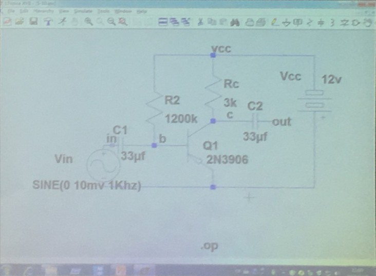
summary
Taking advantage of the high brightness of the screen, we extract the coordinates through binarization to highlight the contour and carry out perspective transformation.
However, the limitation is that if the brightness of the rectangle is not different from the background, it is difficult to detect the contour with this method.