Write in front
Connect to the slave interface, this paper continues to package the IP of an axi4 full master interface, learn the source code, and then simulate the waveform.
Take you to a quick start AXI4 bus -- AXI4 full chapter (2) -- Xilinx AXI4 full interface IP source code simulation analysis (Slave interface) https://blog.csdn.net/wuzhikaidetb/article/details/121594798 https://blog.csdn.net/wuzhikaidetb/article/details/121594798Take you quickly to the AXI4 bus -- Summary (direct link) https://wuzhikai.blog.csdn.net/article/details/121574746
 https://wuzhikai.blog.csdn.net/article/details/121574746
1. Call IP
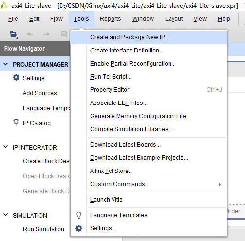
First create a new project, and then click Tools-----create and package new ip
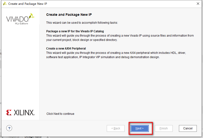
Click Next
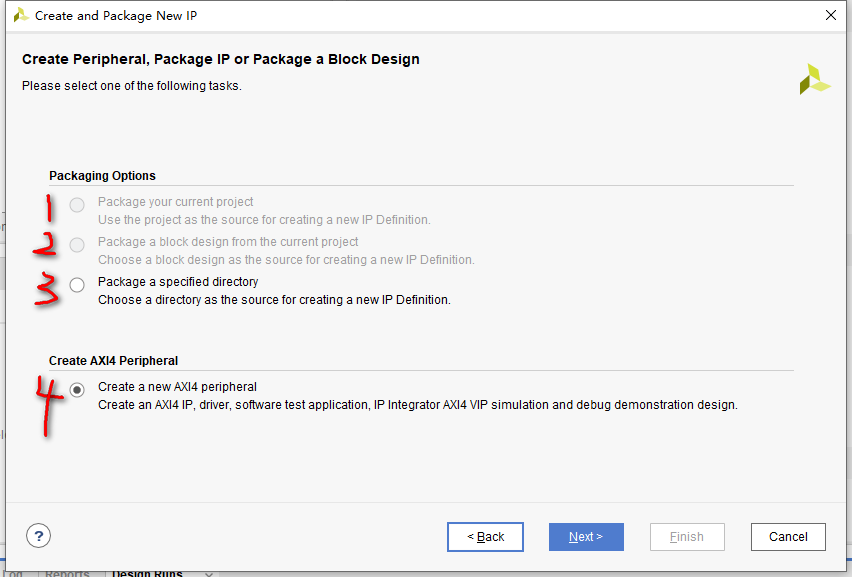
Select option 4 and click Next. The meaning of each option:
- 1 --- package the current project as an IP core
- 2 ---- package the module design of the current project into IP core
- 3 ---- package a specific folder directory as an IP core
- 4 ---- create an IP core with AXI interface
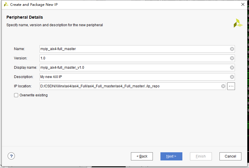
Fill in the IP information (basically no modification, only change the name for subsequent management), and click Next
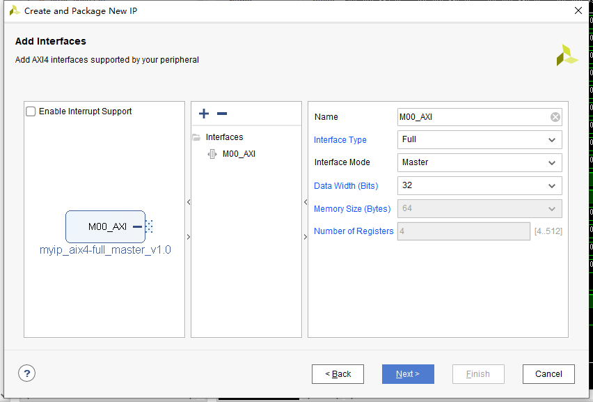
Select the Full interface, select the slave master as the interface type, and the data bit width is 32 bits, and then click Next
Select the third one here, use AXI4 VIP to verify the IP, and then click Next. (AXI4 VIP is an IP core of XILINX, which can provide a variety of connection modes to verify the AXI interface. It is very intimate and convenient to use. Related articles will be written later. Please look forward to it.)
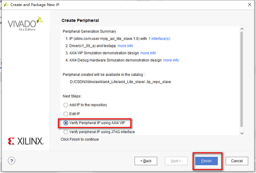
This generates a verification project for the master interface. Don't worry, play with it first. The structure of the whole project is as follows:
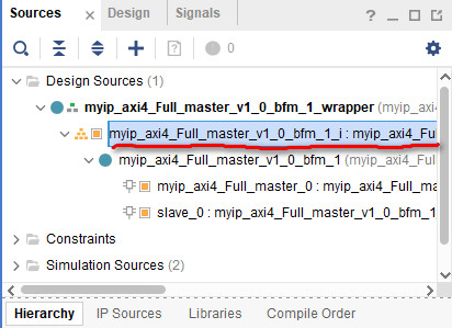
Double click the previous BD module to open the project block diagram as follows:

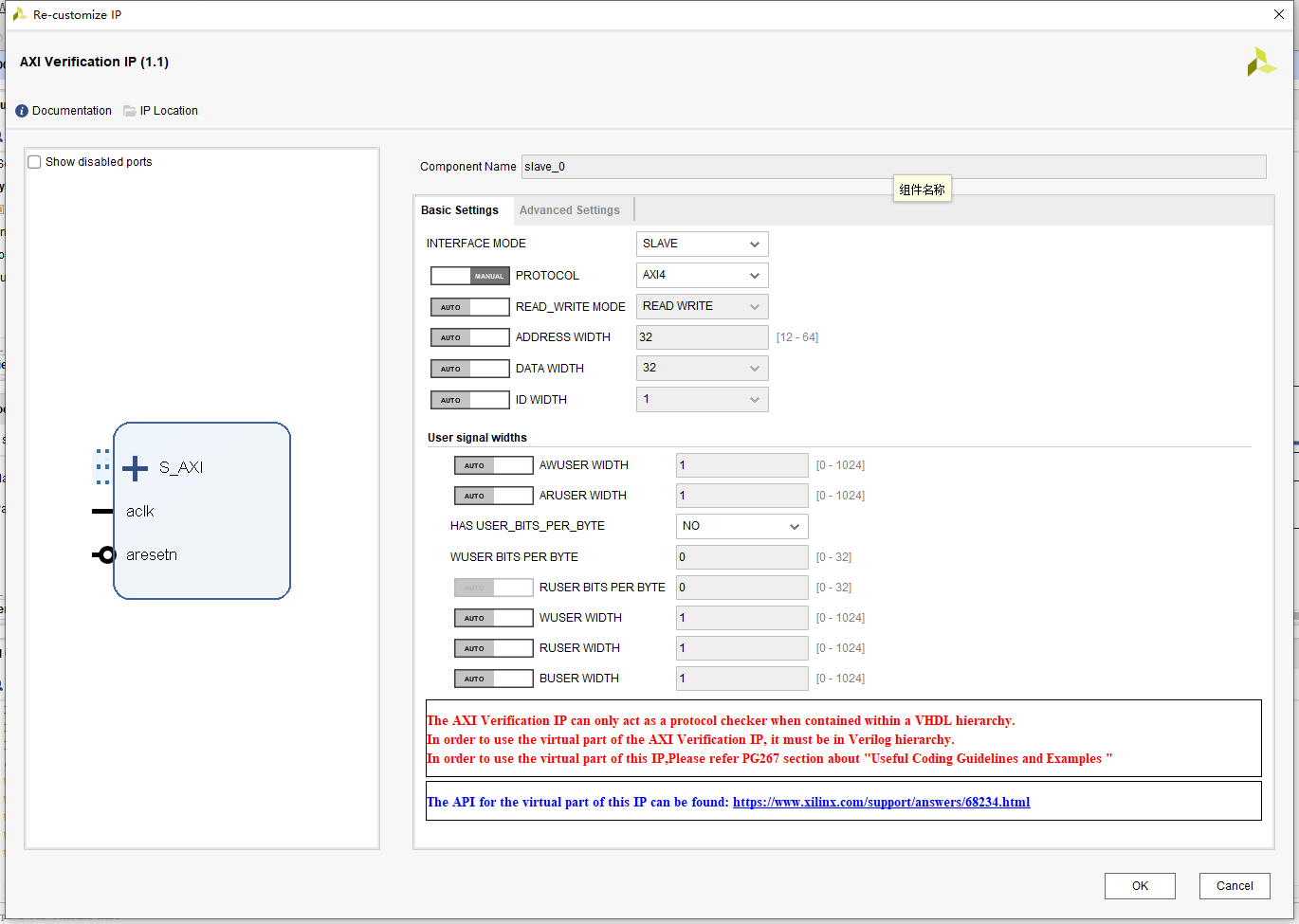
The whole project consists of two parts: 1. Our packaged IP, whose interface is AIX 4 full master; 2. AXI Verification IP, an AXI Verification IP, provides a variety of verification methods and powerful functions. Double click the IP to see its built-in customization information:
It can be seen that it can select the interface mode to realize the master or slave or through function; Optional protocol type, address bit width, data bit width, etc. We don't move it here, just cancel.
2. Source code analysis of Master interface
The generated interface source code is available in the following path:

Next, double-click to open it. Let's find out. (since the source code is 900 lines long, one-time expansion is not conducive to reading, I will explain it in blocks next.)
NO.1 --- module parameters, input and output signals:
The parameters are mainly the bit width of data, address and ID; The base address of the target slave.
The interface is the standard axi4 full interface. If you forget the signal definition, you can see here: Take you to a quick start AXI4 bus -- AXI4 full chapter (1) -- AXI4 full bus
In addition, there are functional interfaces: 1. INIT_AXI_TXN: start sending transaction signal; 2,TXN_DONE: transaction completion signal; 3. ERROR: ERROR signal.
`timescale 1 ns / 1 ps

	module myip_axi4_Full_master_v1_0_M00_AXI #
	(
		// Users to add parameters here

		// User parameters ends
		// Do not modify the parameters beyond this line

		// Base address of targeted slave
		parameter  C_M_TARGET_SLAVE_BASE_ADDR	= 32'h40000000,
		// Burst Length. Supports 1, 2, 4, 8, 16, 32, 64, 128, 256 burst lengths
		parameter integer C_M_AXI_BURST_LEN	= 16,
		// Thread ID Width
		parameter integer C_M_AXI_ID_WIDTH	= 1,
		// Width of Address Bus
		parameter integer C_M_AXI_ADDR_WIDTH	= 32,
		// Width of Data Bus
		parameter integer C_M_AXI_DATA_WIDTH	= 32,
		// Width of User Write Address Bus
		parameter integer C_M_AXI_AWUSER_WIDTH	= 0,
		// Width of User Read Address Bus
		parameter integer C_M_AXI_ARUSER_WIDTH	= 0,
		// Width of User Write Data Bus
		parameter integer C_M_AXI_WUSER_WIDTH	= 0,
		// Width of User Read Data Bus
		parameter integer C_M_AXI_RUSER_WIDTH	= 0,
		// Width of User Response Bus
		parameter integer C_M_AXI_BUSER_WIDTH	= 0
	)
	(
		// Users to add ports here

		// User ports ends
		// Do not modify the ports beyond this line

		// Initiate AXI transactions
		input wire  INIT_AXI_TXN,
		// Asserts when transaction is complete
		output wire  TXN_DONE,
		// Asserts when ERROR is detected
		output reg  ERROR,
		// Global Clock Signal.
		input wire  M_AXI_ACLK,
		// Global Reset Singal. This Signal is Active Low
		input wire  M_AXI_ARESETN,
		// Master Interface Write Address ID
		output wire [C_M_AXI_ID_WIDTH-1 : 0] M_AXI_AWID,
		// Master Interface Write Address
		output wire [C_M_AXI_ADDR_WIDTH-1 : 0] M_AXI_AWADDR,
		// Burst length. The burst length gives the exact number of transfers in a burst
		output wire [7 : 0] M_AXI_AWLEN,
		// Burst size. This signal indicates the size of each transfer in the burst
		output wire [2 : 0] M_AXI_AWSIZE,
		// Burst type. The burst type and the size information,
    // determine how the address for each transfer within the burst is calculated.
		output wire [1 : 0] M_AXI_AWBURST,
		// Lock type. Provides additional information about the
    // atomic characteristics of the transfer.
		output wire  M_AXI_AWLOCK,
		// Memory type. This signal indicates how transactions
    // are required to progress through a system.
		output wire [3 : 0] M_AXI_AWCACHE,
		// Protection type. This signal indicates the privilege
    // and security level of the transaction, and whether
    // the transaction is a data access or an instruction access.
		output wire [2 : 0] M_AXI_AWPROT,
		// Quality of Service, QoS identifier sent for each write transaction.
		output wire [3 : 0] M_AXI_AWQOS,
		// Optional User-defined signal in the write address channel.
		output wire [C_M_AXI_AWUSER_WIDTH-1 : 0] M_AXI_AWUSER,
		// Write address valid. This signal indicates that
    // the channel is signaling valid write address and control information.
		output wire  M_AXI_AWVALID,
		// Write address ready. This signal indicates that
    // the slave is ready to accept an address and associated control signals
		input wire  M_AXI_AWREADY,
		// Master Interface Write Data.
		output wire [C_M_AXI_DATA_WIDTH-1 : 0] M_AXI_WDATA,
		// Write strobes. This signal indicates which byte
    // lanes hold valid data. There is one write strobe
    // bit for each eight bits of the write data bus.
		output wire [C_M_AXI_DATA_WIDTH/8-1 : 0] M_AXI_WSTRB,
		// Write last. This signal indicates the last transfer in a write burst.
		output wire  M_AXI_WLAST,
		// Optional User-defined signal in the write data channel.
		output wire [C_M_AXI_WUSER_WIDTH-1 : 0] M_AXI_WUSER,
		// Write valid. This signal indicates that valid write
    // data and strobes are available
		output wire  M_AXI_WVALID,
		// Write ready. This signal indicates that the slave
    // can accept the write data.
		input wire  M_AXI_WREADY,
		// Master Interface Write Response.
		input wire [C_M_AXI_ID_WIDTH-1 : 0] M_AXI_BID,
		// Write response. This signal indicates the status of the write transaction.
		input wire [1 : 0] M_AXI_BRESP,
		// Optional User-defined signal in the write response channel
		input wire [C_M_AXI_BUSER_WIDTH-1 : 0] M_AXI_BUSER,
		// Write response valid. This signal indicates that the
    // channel is signaling a valid write response.
		input wire  M_AXI_BVALID,
		// Response ready. This signal indicates that the master
    // can accept a write response.
		output wire  M_AXI_BREADY,
		// Master Interface Read Address.
		output wire [C_M_AXI_ID_WIDTH-1 : 0] M_AXI_ARID,
		// Read address. This signal indicates the initial
    // address of a read burst transaction.
		output wire [C_M_AXI_ADDR_WIDTH-1 : 0] M_AXI_ARADDR,
		// Burst length. The burst length gives the exact number of transfers in a burst
		output wire [7 : 0] M_AXI_ARLEN,
		// Burst size. This signal indicates the size of each transfer in the burst
		output wire [2 : 0] M_AXI_ARSIZE,
		// Burst type. The burst type and the size information,
    // determine how the address for each transfer within the burst is calculated.
		output wire [1 : 0] M_AXI_ARBURST,
		// Lock type. Provides additional information about the
    // atomic characteristics of the transfer.
		output wire  M_AXI_ARLOCK,
		// Memory type. This signal indicates how transactions
    // are required to progress through a system.
		output wire [3 : 0] M_AXI_ARCACHE,
		// Protection type. This signal indicates the privilege
    // and security level of the transaction, and whether
    // the transaction is a data access or an instruction access.
		output wire [2 : 0] M_AXI_ARPROT,
		// Quality of Service, QoS identifier sent for each read transaction
		output wire [3 : 0] M_AXI_ARQOS,
		// Optional User-defined signal in the read address channel.
		output wire [C_M_AXI_ARUSER_WIDTH-1 : 0] M_AXI_ARUSER,
		// Write address valid. This signal indicates that
    // the channel is signaling valid read address and control information
		output wire  M_AXI_ARVALID,
		// Read address ready. This signal indicates that
    // the slave is ready to accept an address and associated control signals
		input wire  M_AXI_ARREADY,
		// Read ID tag. This signal is the identification tag
    // for the read data group of signals generated by the slave.
		input wire [C_M_AXI_ID_WIDTH-1 : 0] M_AXI_RID,
		// Master Read Data
		input wire [C_M_AXI_DATA_WIDTH-1 : 0] M_AXI_RDATA,
		// Read response. This signal indicates the status of the read transfer
		input wire [1 : 0] M_AXI_RRESP,
		// Read last. This signal indicates the last transfer in a read burst
		input wire  M_AXI_RLAST,
		// Optional User-defined signal in the read address channel.
		input wire [C_M_AXI_RUSER_WIDTH-1 : 0] M_AXI_RUSER,
		// Read valid. This signal indicates that the channel
    // is signaling the required read data.
		input wire  M_AXI_RVALID,
		// Read ready. This signal indicates that the master can
    // accept the read data and response information.
		output wire  M_AXI_RREADY
	);
NO.2 --- definition of function and register:
It mainly defines the register of the output port of AXI4 to avoid direct operation on the output port;
The function of clogb2: take logarithm based on 2, which is mainly used to calculate bit width.
The state definition of state machine: initial state, sending state, receiving state, comparison (error checking) state.
	// function called clogb2 that returns an integer which has the
	//value of the ceiling of the log base 2

	  // function called clogb2 that returns an integer which has the
	  // value of the ceiling of the log base 2.
	  function integer clogb2 (input integer bit_depth);
	  begin
	    for(clogb2=0; bit_depth>0; clogb2=clogb2+1)
	      bit_depth = bit_depth >> 1;
	    end
	  endfunction

	// C_TRANSACTIONS_NUM is the width of the index counter for
	// number of write or read transaction.
	 localparam integer C_TRANSACTIONS_NUM = clogb2(C_M_AXI_BURST_LEN-1);

	// Burst length for transactions, in C_M_AXI_DATA_WIDTHs.
	// Non-2^n lengths will eventually cause bursts across 4K address boundaries.
	 localparam integer C_MASTER_LENGTH	= 12;
	// total number of burst transfers is master length divided by burst length and burst size
	 localparam integer C_NO_BURSTS_REQ = C_MASTER_LENGTH-clogb2((C_M_AXI_BURST_LEN*C_M_AXI_DATA_WIDTH/8)-1);
	// Example State machine to initialize counter, initialize write transactions,
	// initialize read transactions and comparison of read data with the
	// written data words.
	parameter [1:0] IDLE = 2'b00, // This state initiates AXI4Lite transaction
			// after the state machine changes state to INIT_WRITE
			// when there is 0 to 1 transition on INIT_AXI_TXN
		INIT_WRITE   = 2'b01, // This state initializes write transaction,
			// once writes are done, the state machine
			// changes state to INIT_READ
		INIT_READ = 2'b10, // This state initializes read transaction
			// once reads are done, the state machine
			// changes state to INIT_COMPARE
		INIT_COMPARE = 2'b11; // This state issues the status of comparison
			// of the written data with the read data

	 reg [1:0] mst_exec_state;

	// AXI4LITE signals
	//AXI4 internal temp signals
	reg [C_M_AXI_ADDR_WIDTH-1 : 0] 	axi_awaddr;
	reg  	axi_awvalid;
	reg [C_M_AXI_DATA_WIDTH-1 : 0] 	axi_wdata;
	reg  	axi_wlast;
	reg  	axi_wvalid;
	reg  	axi_bready;
	reg [C_M_AXI_ADDR_WIDTH-1 : 0] 	axi_araddr;
	reg  	axi_arvalid;
	reg  	axi_rready;
	//write beat count in a burst
	reg [C_TRANSACTIONS_NUM : 0] 	write_index;
	//read beat count in a burst
	reg [C_TRANSACTIONS_NUM : 0] 	read_index;
	//size of C_M_AXI_BURST_LEN length burst in bytes
	wire [C_TRANSACTIONS_NUM+2 : 0] 	burst_size_bytes;
	//The burst counters are used to track the number of burst transfers of C_M_AXI_BURST_LEN burst length needed to transfer 2^C_MASTER_LENGTH bytes of data.
	reg [C_NO_BURSTS_REQ : 0] 	write_burst_counter;
	reg [C_NO_BURSTS_REQ : 0] 	read_burst_counter;
	reg  	start_single_burst_write;
	reg  	start_single_burst_read;
	reg  	writes_done;
	reg  	reads_done;
	reg  	error_reg;
	reg  	compare_done;
	reg  	read_mismatch;
	reg  	burst_write_active;
	reg  	burst_read_active;
	reg [C_M_AXI_DATA_WIDTH-1 : 0] 	expected_rdata;
	//Interface response error flags
	wire  	write_resp_error;
	wire  	read_resp_error;
	wire  	wnext;
	wire  	rnext;
	reg  	init_txn_ff;
	reg  	init_txn_ff2;
	reg  	init_txn_edge;
	wire  	init_txn_pulse;
No.3 --- wire signal assignment:
Assign a value to the output signal of AXI4 to avoid direct operation.
	// I/O Connections assignments

	//I/O Connections. Write Address (AW)
	assign M_AXI_AWID	= 'b0;
	//The AXI address is a concatenation of the target base address + active offset range
	assign M_AXI_AWADDR	= C_M_TARGET_SLAVE_BASE_ADDR + axi_awaddr;
	//Burst LENgth is number of transaction beats, minus 1
	assign M_AXI_AWLEN	= C_M_AXI_BURST_LEN - 1;
	//Size should be C_M_AXI_DATA_WIDTH, in 2^SIZE bytes, otherwise narrow bursts are used
	assign M_AXI_AWSIZE	= clogb2((C_M_AXI_DATA_WIDTH/8)-1);
	//INCR burst type is usually used, except for keyhole bursts
	assign M_AXI_AWBURST	= 2'b01;
	assign M_AXI_AWLOCK	= 1'b0;
	//Update value to 4'b0011 if coherent accesses to be used via the Zynq ACP port. Not Allocated, Modifiable, not Bufferable. Not Bufferable since this example is meant to test memory, not intermediate cache.
	assign M_AXI_AWCACHE	= 4'b0010;
	assign M_AXI_AWPROT	= 3'h0;
	assign M_AXI_AWQOS	= 4'h0;
	assign M_AXI_AWUSER	= 'b1;
	assign M_AXI_AWVALID	= axi_awvalid;
	//Write Data(W)
	assign M_AXI_WDATA	= axi_wdata;
	//All bursts are complete and aligned in this example
	assign M_AXI_WSTRB	= {(C_M_AXI_DATA_WIDTH/8){1'b1}};
	assign M_AXI_WLAST	= axi_wlast;
	assign M_AXI_WUSER	= 'b0;
	assign M_AXI_WVALID	= axi_wvalid;
	//Write Response (B)
	assign M_AXI_BREADY	= axi_bready;
	//Read Address (AR)
	assign M_AXI_ARID	= 'b0;
	assign M_AXI_ARADDR	= C_M_TARGET_SLAVE_BASE_ADDR + axi_araddr;
	//Burst LENgth is number of transaction beats, minus 1
	assign M_AXI_ARLEN	= C_M_AXI_BURST_LEN - 1;
	//Size should be C_M_AXI_DATA_WIDTH, in 2^n bytes, otherwise narrow bursts are used
	assign M_AXI_ARSIZE	= clogb2((C_M_AXI_DATA_WIDTH/8)-1);
	//INCR burst type is usually used, except for keyhole bursts
	assign M_AXI_ARBURST	= 2'b01;
	assign M_AXI_ARLOCK	= 1'b0;
	//Update value to 4'b0011 if coherent accesses to be used via the Zynq ACP port. Not Allocated, Modifiable, not Bufferable. Not Bufferable since this example is meant to test memory, not intermediate cache.
	assign M_AXI_ARCACHE	= 4'b0010;
	assign M_AXI_ARPROT	= 3'h0;
	assign M_AXI_ARQOS	= 4'h0;
	assign M_AXI_ARUSER	= 'b1;
	assign M_AXI_ARVALID	= axi_arvalid;
	//Read and Read Response (R)
	assign M_AXI_RREADY	= axi_rready;
	//Example design I/O
	assign TXN_DONE	= compare_done;
	//Burst size in bytes
	assign burst_size_bytes	= C_M_AXI_BURST_LEN * C_M_AXI_DATA_WIDTH/8;
NO.4 ---- capture the rising edge of the write transaction start signal:
Write transaction start signal INIT_AXI_TXN beats and captures its rising edge as a flag signal to start transmission.
	assign init_txn_pulse	= (!init_txn_ff2) && init_txn_ff;
	//Generate a pulse to initiate AXI transaction.
	always @(posedge M_AXI_ACLK)
	  begin
	    // Initiates AXI transaction delay
	    if (M_AXI_ARESETN == 0 )
	      begin
	        init_txn_ff <= 1'b0;
	        init_txn_ff2 <= 1'b0;
	      end
	    else
	      begin
	        init_txn_ff <= INIT_AXI_TXN;
	        init_txn_ff2 <= init_txn_ff;
	      end
	  end
NO.5 --- write address channel:
Write address preparation signal axi_awvalid: when a single burst write signal starts_ single_ burst_ When write is valid, pull it up.
When the write address channel handshake is successful, the first address Axi is updated at the same time_ Awaddr assignment.
	  always @(posedge M_AXI_ACLK)
	  begin

	    if (M_AXI_ARESETN == 0 || init_txn_pulse == 1'b1 )
	      begin
	        axi_awvalid <= 1'b0;
	      end
	    // If previously not valid , start next transaction
	    else if (~axi_awvalid && start_single_burst_write)
	      begin
	        axi_awvalid <= 1'b1;
	      end
	    /* Once asserted, VALIDs cannot be deasserted, so axi_awvalid
	    must wait until transaction is accepted */
	    else if (M_AXI_AWREADY && axi_awvalid)
	      begin
	        axi_awvalid <= 1'b0;
	      end
	    else
	      axi_awvalid <= axi_awvalid;
	    end


	// Next address after AWREADY indicates previous address acceptance
	  always @(posedge M_AXI_ACLK)
	  begin
	    if (M_AXI_ARESETN == 0 || init_txn_pulse == 1'b1)
	      begin
	        axi_awaddr <= 'b0;
	      end
	    else if (M_AXI_AWREADY && axi_awvalid)
	      begin
	        axi_awaddr <= axi_awaddr + burst_size_bytes;
	      end
	    else
	      axi_awaddr <= axi_awaddr;
NO.6 --- write data channel:
Write data preparation signal axi_wvalid: when a single burst write signal starts_ single_ burst_ When write is valid, pull it up.
Pull up Axi when writing the last data_ wlast.
Each time a data is written, the burst write length counter writes_ Index accumulation 1
Axi during data writing_ Wdata accumulates 1 from 0
	  assign wnext = M_AXI_WREADY & axi_wvalid;   	//Write data duration

	// WVALID logic, similar to the axi_awvalid always block above
	  always @(posedge M_AXI_ACLK)
	  begin
	    if (M_AXI_ARESETN == 0 || init_txn_pulse == 1'b1 )
	      begin
	        axi_wvalid <= 1'b0;
	      end
	    // If previously not valid, start next transaction
	    else if (~axi_wvalid && start_single_burst_write)
	      begin
	        axi_wvalid <= 1'b1;
	      end
	    /* If WREADY and too many writes, throttle WVALID
	    Once asserted, VALIDs cannot be deasserted, so WVALID
	    must wait until burst is complete with WLAST */
	    else if (wnext && axi_wlast)
	      axi_wvalid <= 1'b0;
	    else
	      axi_wvalid <= axi_wvalid;
	  end


	//WLAST generation on the MSB of a counter underflow
	// WVALID logic, similar to the axi_awvalid always block above
	  always @(posedge M_AXI_ACLK)
	  begin
	    if (M_AXI_ARESETN == 0 || init_txn_pulse == 1'b1 )
	      begin
	        axi_wlast <= 1'b0;
	      end
	    // axi_wlast is asserted when the write index
	    // count reaches the penultimate count to synchronize
	    // with the last write data when write_index is b1111
	    // else if (&(write_index[C_TRANSACTIONS_NUM-1:1])&& ~write_index[0] && wnext)
	    else if (((write_index == C_M_AXI_BURST_LEN-2 && C_M_AXI_BURST_LEN >= 2) && wnext) || (C_M_AXI_BURST_LEN == 1 ))
	      begin
	        axi_wlast <= 1'b1;
	      end
	    // Deassrt axi_wlast when the last write data has been
	    // accepted by the slave with a valid response
	    else if (wnext)
	      axi_wlast <= 1'b0;
	    else if (axi_wlast && C_M_AXI_BURST_LEN == 1)
	      axi_wlast <= 1'b0;
	    else
	      axi_wlast <= axi_wlast;
	  end


	/* Burst length counter. Uses extra counter register bit to indicate terminal
	 count to reduce decode logic */
	  always @(posedge M_AXI_ACLK)
	  begin
	    if (M_AXI_ARESETN == 0 || init_txn_pulse == 1'b1 || start_single_burst_write == 1'b1)
	      begin
	        write_index <= 0;
	      end
	    else if (wnext && (write_index != C_M_AXI_BURST_LEN-1))
	      begin
	        write_index <= write_index + 1;
	      end
	    else
	      write_index <= write_index;
	  end


	/* Write Data Generator
	 Data pattern is only a simple incrementing count from 0 for each burst  */
	  always @(posedge M_AXI_ACLK)
	  begin
	    if (M_AXI_ARESETN == 0 || init_txn_pulse == 1'b1)
	      axi_wdata <= 'b1;
	    //else if (wnext && axi_wlast)
	    //  axi_wdata <= 'b0;
	    else if (wnext)
	      axi_wdata <= axi_wdata + 1;
	    else
	      axi_wdata <= axi_wdata;
	    end
NO.7 --- write response channel:
Write response preparation signal axi_bready: when the slave sends M_ AXI_ When bvalid is valid, pull it up.
Write response error signal write_resp_error: when the received write response is incorrect, pull it up.
	  always @(posedge M_AXI_ACLK)
	  begin
	    if (M_AXI_ARESETN == 0 || init_txn_pulse == 1'b1 )
	      begin
	        axi_bready <= 1'b0;
	      end
	    // accept/acknowledge bresp with axi_bready by the master
	    // when M_AXI_BVALID is asserted by slave
	    else if (M_AXI_BVALID && ~axi_bready)
	      begin
	        axi_bready <= 1'b1;
	      end
	    // deassert after one clock cycle
	    else if (axi_bready)
	      begin
	        axi_bready <= 1'b0;
	      end
	    // retain the previous value
	    else
	      axi_bready <= axi_bready;
	  end


	//Flag any write response errors
	  assign write_resp_error = axi_bready & M_AXI_BVALID & M_AXI_BRESP[1];
NO.8 --- read address channel:
Read address preparation signal axi_arvalid: when the single burst read signal starts_ single_ burst_ When read is valid, pull it up.
When the handshake of the read address channel is successful, the first address Axi is updated at the same time_ Araddr assignment.
	  always @(posedge M_AXI_ACLK)
	  begin

	    if (M_AXI_ARESETN == 0 || init_txn_pulse == 1'b1 )
	      begin
	        axi_arvalid <= 1'b0;
	      end
	    // If previously not valid , start next transaction
	    else if (~axi_arvalid && start_single_burst_read)
	      begin
	        axi_arvalid <= 1'b1;
	      end
	    else if (M_AXI_ARREADY && axi_arvalid)
	      begin
	        axi_arvalid <= 1'b0;
	      end
	    else
	      axi_arvalid <= axi_arvalid;
	  end


	// Next address after ARREADY indicates previous address acceptance
	  always @(posedge M_AXI_ACLK)
	  begin
	    if (M_AXI_ARESETN == 0 || init_txn_pulse == 1'b1)
	      begin
	        axi_araddr <= 'b0;
	      end
	    else if (M_AXI_ARREADY && axi_arvalid)
	      begin
	        axi_araddr <= axi_araddr + burst_size_bytes;
	      end
	    else
	      axi_araddr <= axi_araddr;
	  end
NO.9 --- read data channel:
Read data preparation signal axi_rready: when the last data is read, pull it down, and when the slave sends the read valid signal M_ AXI_ Pull the rvalid up when it is valid.
Each time a data is read, the burst read length counter reads_ Index adds up to 1.
Read mismatch signal read_mismatch: when the read data is inconsistent with the expected read data (written data), pull it up.
Read response error signal read_resp_error: once the read response value is illegal, it will be pulled up.
Expected read data expected_rdata: the data expected to be read, that is, the data to be written.
Error signal error_reg: once the following three errors are met, it will be raised: 1. Write response error; 2. Read response error; 3. Read and write contents do not match.
	 // Forward movement occurs when the channel is valid and ready
	  assign rnext = M_AXI_RVALID && axi_rready;     		//Read data period


	// Burst length counter. Uses extra counter register bit to indicate
	// terminal count to reduce decode logic
	  always @(posedge M_AXI_ACLK)
	  begin
	    if (M_AXI_ARESETN == 0 || init_txn_pulse == 1'b1 || start_single_burst_read)
	      begin
	        read_index <= 0;
	      end
	    else if (rnext && (read_index != C_M_AXI_BURST_LEN-1))
	      begin
	        read_index <= read_index + 1;
	      end
	    else
	      read_index <= read_index;
	  end


	/*
	 The Read Data channel returns the results of the read request

	 In this example the data checker is always able to accept
	 more data, so no need to throttle the RREADY signal
	 */
	  always @(posedge M_AXI_ACLK)
	  begin
	    if (M_AXI_ARESETN == 0 || init_txn_pulse == 1'b1 )
	      begin
	        axi_rready <= 1'b0;
	      end
	    // accept/acknowledge rdata/rresp with axi_rready by the master
	    // when M_AXI_RVALID is asserted by slave
	    else if (M_AXI_RVALID)
	      begin
	         if (M_AXI_RLAST && axi_rready)
	          begin
	            axi_rready <= 1'b0;
	          end
	         else
	           begin
	             axi_rready <= 1'b1;
	           end
	      end
	    // retain the previous value
	  end

	//Check received read data against data generator
	  always @(posedge M_AXI_ACLK)
	  begin
	    if (M_AXI_ARESETN == 0 || init_txn_pulse == 1'b1)
	      begin
	        read_mismatch <= 1'b0;
	      end
	    //Only check data when RVALID is active
	    else if (rnext && (M_AXI_RDATA != expected_rdata))
	      begin
	        read_mismatch <= 1'b1;
	      end
	    else
	      read_mismatch <= 1'b0;
	  end

	//Flag any read response errors
	  assign read_resp_error = axi_rready & M_AXI_RVALID & M_AXI_RRESP[1];

	//----------------------------------------
	//Example design read check data generator
	//-----------------------------------------

	//Generate expected read data to check against actual read data

	  always @(posedge M_AXI_ACLK)
	  begin
		if (M_AXI_ARESETN == 0 || init_txn_pulse == 1'b1)// || M_AXI_RLAST)
			expected_rdata <= 'b1;
		else if (M_AXI_RVALID && axi_rready)
			expected_rdata <= expected_rdata + 1;
		else
			expected_rdata <= expected_rdata;
	  end
	//----------------------------------
	//Example design error register
	//----------------------------------

	//Register and hold any data mismatches, or read/write interface errors

	  always @(posedge M_AXI_ACLK)
	  begin
	    if (M_AXI_ARESETN == 0 || init_txn_pulse == 1'b1)
	      begin
	        error_reg <= 1'b0;
	      end
	    else if (read_mismatch || write_resp_error || read_resp_error)
	      begin
	        error_reg <= 1'b1;
	      end
	    else
	      error_reg <= error_reg;
	  end
NO.10 --- read and write burst length count:
Read and write burst length count signal read_burst_counter,write_burst_counter counts the number of reads and writes during reading and writing.
	 // write_burst_counter counter keeps track with the number of burst transaction initiated
	 // against the number of burst transactions the master needs to initiate
	  always @(posedge M_AXI_ACLK)
	  begin
	    if (M_AXI_ARESETN == 0 || init_txn_pulse == 1'b1 )
	      begin
	        write_burst_counter <= 'b0;
	      end
	    else if (M_AXI_AWREADY && axi_awvalid)
	      begin
	        if (write_burst_counter[C_NO_BURSTS_REQ] == 1'b0)
	          begin
	            write_burst_counter <= write_burst_counter + 1'b1;
	            //write_burst_counter[C_NO_BURSTS_REQ] <= 1'b1;
	          end
	      end
	    else
	      write_burst_counter <= write_burst_counter;
	  end

	 // read_burst_counter counter keeps track with the number of burst transaction initiated
	 // against the number of burst transactions the master needs to initiate
	  always @(posedge M_AXI_ACLK)
	  begin
	    if (M_AXI_ARESETN == 0 || init_txn_pulse == 1'b1)
	      begin
	        read_burst_counter <= 'b0;
	      end
	    else if (M_AXI_ARREADY && axi_arvalid)
	      begin
	        if (read_burst_counter[C_NO_BURSTS_REQ] == 1'b0)
	          begin
	            read_burst_counter <= read_burst_counter + 1'b1;
	            //read_burst_counter[C_NO_BURSTS_REQ] <= 1'b1;
	          end
	      end
	    else
	      read_burst_counter <= read_burst_counter;
	  end
NO.11 --- process control state machine:
The state machine has four states:
IDLE: initial state. Once the write transaction starts, the signal init_ txn_ The pulse is valid, that is, it enters the write transaction state INIT_WRITE
INIT_WRITE: write transaction status, in which 64 burst write transactions with a length of 16 are completed. Once all write transactions are completed, it enters the read transaction state INIT_READ
INIT_READ: read transaction status, in which 64 burst read transactions with a length of 16 are completed. Once all read transactions are completed, the comparison state init is entered_ COMPARE
INIT_COMPARE: compare the status (comparison error), judge whether there is an error (read-write mismatch, write response error or read response error), and then jump back to the initial status IDLE
	  //implement master command interface state machine

	  always @ ( posedge M_AXI_ACLK)
	  begin
	    if (M_AXI_ARESETN == 1'b0 )
	      begin
	        // reset condition
	        // All the signals are assigned default values under reset condition
	        mst_exec_state      <= IDLE;
	        start_single_burst_write <= 1'b0;
	        start_single_burst_read  <= 1'b0;
	        compare_done      <= 1'b0;
	        ERROR <= 1'b0;
	      end
	    else
	      begin

	        // state transition
	        case (mst_exec_state)

	          IDLE:
	            // This state is responsible to wait for user defined C_M_START_COUNT
	            // number of clock cycles.
	            if ( init_txn_pulse == 1'b1)
	              begin
	                mst_exec_state  <= INIT_WRITE;
	                ERROR <= 1'b0;
	                compare_done <= 1'b0;
	              end
	            else
	              begin
	                mst_exec_state  <= IDLE;
	              end

	          INIT_WRITE:
	            // This state is responsible to issue start_single_write pulse to
	            // initiate a write transaction. Write transactions will be
	            // issued until burst_write_active signal is asserted.
	            // write controller
	            if (writes_done)
	              begin
	                mst_exec_state <= INIT_READ;//
	              end
	            else
	              begin
	                mst_exec_state  <= INIT_WRITE;

	                if (~axi_awvalid && ~start_single_burst_write && ~burst_write_active)
	                  begin
	                    start_single_burst_write <= 1'b1;
	                  end
	                else
	                  begin
	                    start_single_burst_write <= 1'b0; //Negate to generate a pulse
	                  end
	              end

	          INIT_READ:
	            // This state is responsible to issue start_single_read pulse to
	            // initiate a read transaction. Read transactions will be
	            // issued until burst_read_active signal is asserted.
	            // read controller
	            if (reads_done)
	              begin
	                mst_exec_state <= INIT_COMPARE;
	              end
	            else
	              begin
	                mst_exec_state  <= INIT_READ;

	                if (~axi_arvalid && ~burst_read_active && ~start_single_burst_read)
	                  begin
	                    start_single_burst_read <= 1'b1;
	                  end
	               else
	                 begin
	                   start_single_burst_read <= 1'b0; //Negate to generate a pulse
	                 end
	              end

	          INIT_COMPARE:
	            // This state is responsible to issue the state of comparison
	            // of written data with the read data. If no error flags are set,
	            // compare_done signal will be asseted to indicate success.
	            //if (~error_reg)
	            begin
	              ERROR <= error_reg;
	              mst_exec_state <= IDLE;
	              compare_done <= 1'b1;
	            end
	          default :
	            begin
	              mst_exec_state  <= IDLE;
	            end
	        endcase
	      end
	  end //MASTER_EXECUTION_PROC
NO.11 - burst read / write status management:
burst_write_active: burst write effective signal. When it is pulled high, it indicates that a burst write process is in progress
burst_read_active: burst read effective signal. When it is pulled high, it means that a burst read process is in progress
writes_done: the completion signal of all write transactions. Pull it up after all write transactions are completed
reads_done: the completion signal of all read transactions. Pull it up after all read transactions are completed
	  // burst_write_active signal is asserted when there is a burst write transaction
	  // is initiated by the assertion of start_single_burst_write. burst_write_active
	  // signal remains asserted until the burst write is accepted by the slave
	  always @(posedge M_AXI_ACLK)
	  begin
	    if (M_AXI_ARESETN == 0 || init_txn_pulse == 1'b1)
	      burst_write_active <= 1'b0;

	    //The burst_write_active is asserted when a write burst transaction is initiated
	    else if (start_single_burst_write)
	      burst_write_active <= 1'b1;
	    else if (M_AXI_BVALID && axi_bready)
	      burst_write_active <= 0;
	  end

	 // Check for last write completion.

	 // This logic is to qualify the last write count with the final write
	 // response. This demonstrates how to confirm that a write has been
	 // committed.

	  always @(posedge M_AXI_ACLK)
	  begin
	    if (M_AXI_ARESETN == 0 || init_txn_pulse == 1'b1)
	      writes_done <= 1'b0;

	    //The writes_done should be associated with a bready response
	    //else if (M_AXI_BVALID && axi_bready && (write_burst_counter == {(C_NO_BURSTS_REQ-1){1}}) && axi_wlast)
	    else if (M_AXI_BVALID && (write_burst_counter[C_NO_BURSTS_REQ]) && axi_bready)
	      writes_done <= 1'b1;
	    else
	      writes_done <= writes_done;
	    end

	  // burst_read_active signal is asserted when there is a burst write transaction
	  // is initiated by the assertion of start_single_burst_write. start_single_burst_read
	  // signal remains asserted until the burst read is accepted by the master
	  always @(posedge M_AXI_ACLK)
	  begin
	    if (M_AXI_ARESETN == 0 || init_txn_pulse == 1'b1)
	      burst_read_active <= 1'b0;

	    //The burst_write_active is asserted when a write burst transaction is initiated
	    else if (start_single_burst_read)
	      burst_read_active <= 1'b1;
	    else if (M_AXI_RVALID && axi_rready && M_AXI_RLAST)
	      burst_read_active <= 0;
	    end


	 // Check for last read completion.

	 // This logic is to qualify the last read count with the final read
	 // response. This demonstrates how to confirm that a read has been
	 // committed.

	  always @(posedge M_AXI_ACLK)
	  begin
	    if (M_AXI_ARESETN == 0 || init_txn_pulse == 1'b1)
	      reads_done <= 1'b0;

	    //The reads_done should be associated with a rready response
	    //else if (M_AXI_BVALID && axi_bready && (write_burst_counter == {(C_NO_BURSTS_REQ-1){1}}) && axi_wlast)
	    else if (M_AXI_RVALID && axi_rready && (read_index == C_M_AXI_BURST_LEN-1) && (read_burst_counter[C_NO_BURSTS_REQ]))
	      reads_done <= 1'b1;
	    else
	      reads_done <= reads_done;
	    end

	// Add user logic here

	// User logic ends

	endmodule
3. Simulation waveform
Next, use Vivado's own simulator to simulate and watch the simulation results.
3.1 simulation waveform of axi4 full bus
We first delete the automatically generated simulation signal and add the following waveform signal:
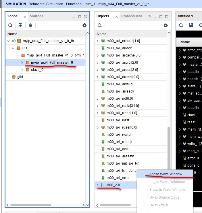
The simulation results are as follows:
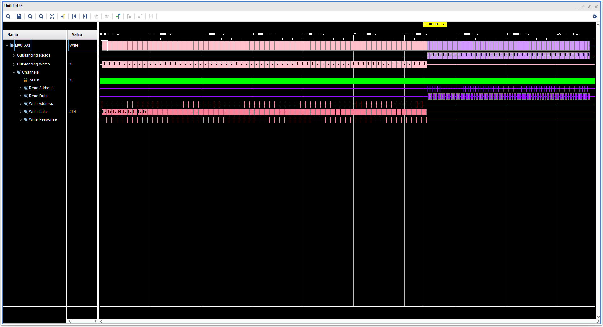
It can be seen that the simulation results are expressed in the form of color bar + character, which is very clear. This is the effect of adding AXI VIP IP.
Multiple transactions occur on the axi4 full bus: first multiple write transactions, and then multiple read transactions. The following five channels respectively illustrate the handshake operation performed in the channel at this time. Place the mouse on any one of them (take the last write transaction as an example), and the following information will appear (sequence 64, address' h40000FC0, burst type incremental burst, burst length 16, burst size 4 BYTES, etc.):
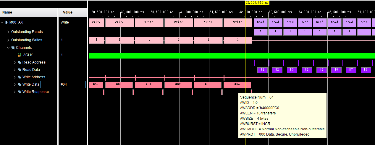
Left click to display the specific transaction flow as follows: write address - write data - write response.

Then place the mouse over the last read transaction and observe the relevant information of the read transaction, as follows:

It can be seen that the relevant information of the last read transaction is consistent with that of the last write transaction, which means that the written data is consistent with the read data in theory.
Click this read transaction again and observe its implementation process: read address - read data (including read response).

3.2 simulation waveform of master interface of host IP
After reading the simulation waveform of axi4 full bus, let's take a look at the simulation waveform of the above specific analysis code (which can be understood as the underlying driver). Add as follows:
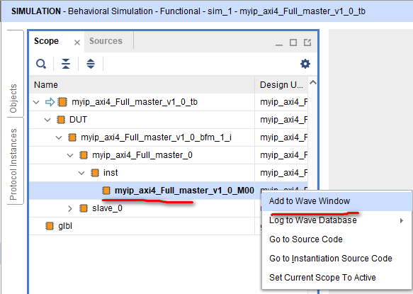
Classify the signals according to channel or purpose, and the simulation results of write transactions (there are 64 write transactions in total, limited to space, only screenshot 2 write transactions) are as follows:
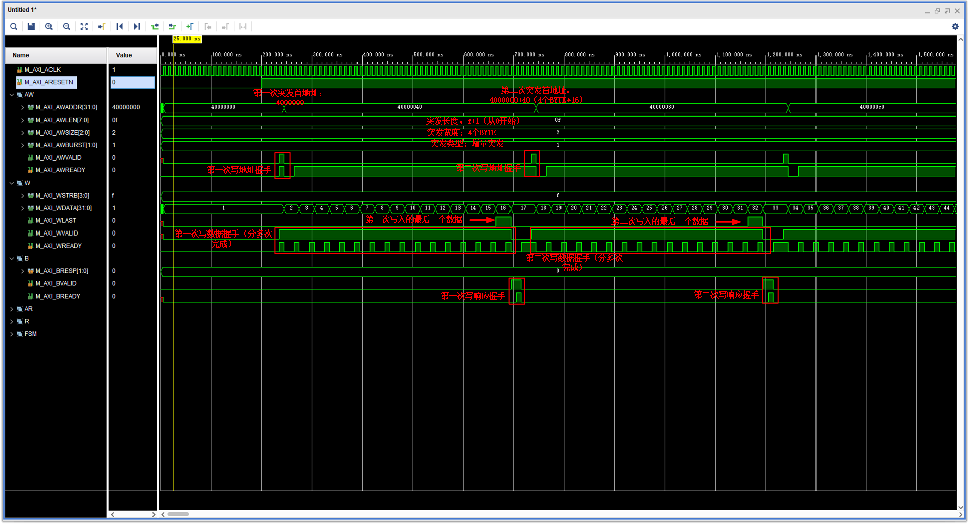
The simulation results of read transactions (there are 64 read transactions in total, limited to space, only screenshot 2 read transactions) are as follows:
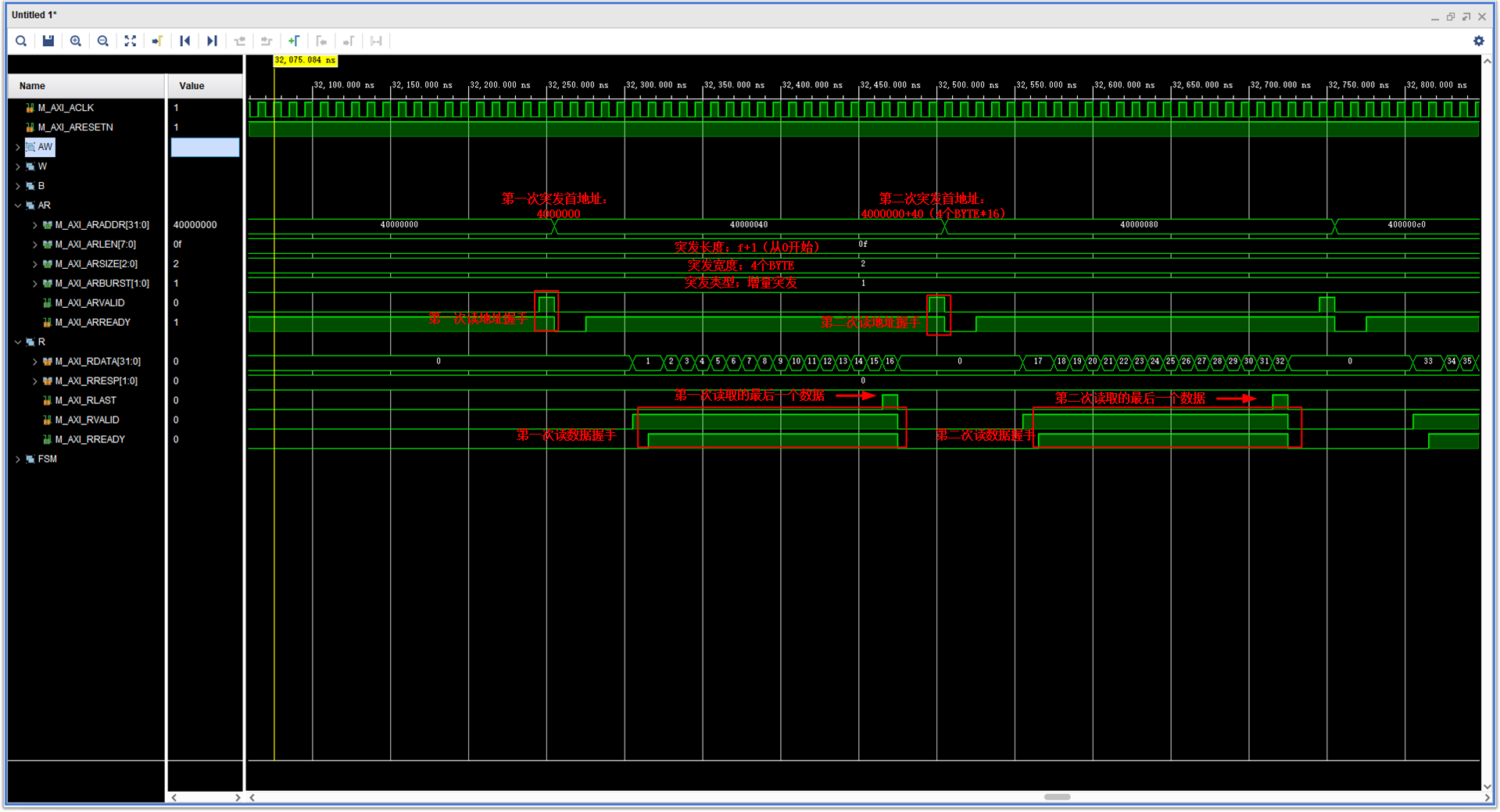
The written data is consistent with the read data.
4. Other
- It can be seen that the use of AXI4 full bus is relatively simple. As long as the handshake timing of each channel and the timing relationship of reading and writing are designed. The AXI4 series is over for the time being.
- It's not easy to create. I hope you guys can support it for three times! If there is any mistake, please correct it!
Version information
File: V1.0
No.: 67
Vivado: Vivado 2019.2
Modelsim: None
Quartus II: None