This article is one of the Apollo project series articles. It will analyze the Routing module in combination with the source code.
preface
For readers who are new to the Apollo project, you can read another article in my blog - Analysis of Baidu Apollo autopilot platform , there is an overall introduction to the Apollo project. It is recommended to browse that article before reading this article.
The source code of Apollo project can be obtained from github: ApolloAuto/apollo.
The source code posted in this article is from the version at the end of 2018 (December 27).
Module introduction
As its name indicates, the Routing module is mainly used to generate Routing information according to requests.
Module input:
- Map data
- Request, including: start and end positions
Module output:
- Route navigation information
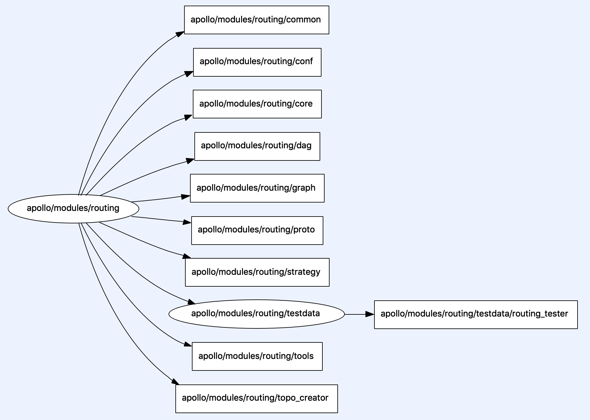
The implementation file structure of Routing module is shown in the following figure:
Constant definition
The Apollo project uses Google's gflags project to define constants. About gflags, you can visit the following two links:
The relevant codes in Routing are as follows. They are located in the header file and the implementation file, respectively.
- routing_gflags.h Document content:
#pragma once

#include "gflags/gflags.h"

DECLARE_string(routing_conf_file);
DECLARE_string(routing_node_name);

DECLARE_double(min_length_for_lane_change);
DECLARE_bool(enable_change_lane_in_result);
DECLARE_uint32(routing_response_history_interval_ms);
- routing_gflags.cc Document content:
#include "modules/routing/common/routing_gflags.h"

DEFINE_string(routing_conf_file,
              "/apollo/modules/routing/conf/routing_config.pb.txt",
              "default routing conf data file");

DEFINE_string(routing_node_name, "routing", "the name for this node");

DEFINE_double(min_length_for_lane_change, 1.0,
              "meters, which is 100 feet.  Minimum distance needs to travel on "
              "a lane before making a lane change. Recommended by "
              "https://www.oregonlaws.org/ors/811.375");

DEFINE_bool(enable_change_lane_in_result, true,
            "contain change lane operator in result");

DEFINE_uint32(routing_response_history_interval_ms, 3000,
              "ms, emit routing resposne for this time interval");
Even if you haven't touched gflags, this code should be easy to understand. Here, you define five constants and specify their values, as well as the description of each constant. The five constants are:
- routing_conf_file: the path to the Routing module configuration file.
- routing_node_name: node name of Routing module.
- min_length_for_lane_change: the shortest distance traveled in the current lane before changing lanes.
- enable_change_lane_in_result: whether the navigation result allows lane change.
- routing_response_history_interval_ms: response time of routing request.
Defining several constants commonly used in the module together can facilitate modification and use in the module.
For example, in the code of the Routing module, flags is used_ Routing_ conf_ File can read the value "/ apollo/modules/routing/conf/routing_config.pb.txt".
This is the configuration file path of the Routing module. The contents of the document are as follows:
base_speed: 4.167
left_turn_penalty: 50.0
right_turn_penalty: 20.0
uturn_penalty: 100.0
change_penalty: 500.0
base_changing_length: 50.0
The role of this configuration file will be mentioned later.
Proto data structure
Many data structures in the Apollo project are through Protocol Buffers Defined. So you can't see the C + + files of these classes, because the relevant files required by C + + are automatically generated through the proto file at compile time.
Protocol Buffers It's Google's open source project. It has the characteristics of language independent and platform independent, and has good scalability. Protocol Buffers are typically used to serialize structured data.
A very important role of Apollo in using Protocol Buffers is to export structured data to physical files, and it can also easily read information from physical files. For example, the Topo map required by the Routing module is derived from the proto structure. In addition, if Exported as text The file can also be easily modified artificially. For example, the routing mentioned above_ config. pb. txt.
The proto files are located in the folder named proto. You can usually find all the proto folders in the root directory of the apollo source code with the following command:
apollo$ find . -name proto
This naturally contains the proto folder of the Routing module: modules/routing/proto .
This directory contains four proto files, and each file contains several structures. These structures are described as follows:
poi.proto
| Type name | describe |
|---|---|
| Landmark | A point on a map that contains name and location information. |
| POI | The abbreviation of Point of interest. A POI can contain multiple landmarks. |
routing_config.proto
| Type name | describe |
|---|---|
| RoutingConfig | Describes the configuration information of the Routing module_ config. pb. Txt file is in this format. |
routing.proto
| Type name | describe |
|---|---|
| LaneWaypoint | The path point on the road contains id, length and location information. |
| LaneSegment | A section of a road that contains id and start stop information. |
| RoutingRequest | Describes the information of the routing request. A routing request can contain multiple path points. The detailed structure is shown below. |
| Measurement | Describe the measured distance. |
| ChangeLaneType | There are three types of roads, FORWARD, LEFT and RIGHT. |
| Passage | A path that can contain multiple lanesegments and ChangeLaneType. |
| RoadSegment | A section of a road has an id and can contain multiple passes. |
| RoutingResponse | The response result of the routing request can contain multiple roadsegments, distances and other information. |
topo_graph.proto
| Type name | describe |
|---|---|
| CurvePoint | A point on a curve. |
| CurveRange | A section of a curve. |
| Node | A node on the lane, including the lane, road, length, curve start and end points, centerline and other information. |
| Edge | The edge between connecting lanes contains information such as start and stop Lane id, cost and direction. |
| Graph | The Topo structure of the complete map, which contains multiple nodes and edges. |
Proto files do not exist in isolation. Each proto file can use the structure defined in other files through import syntax.
For example, the data structures required by the Routing module and other modules are defined in modules/common/proto/ Directory. This includes the following proto files:
.
├── drive_event.proto
├── drive_state.proto
├── error_code.proto
├── geometry.proto
├── header.proto
├── pnc_point.proto
└── vehicle_signal.proto
Due to space constraints, we will not continue here. Interested readers can browse these documents by themselves.
Topo map
In order to calculate the Routing path, a series of classes are included in the Routing module to describe the detailed structure of the Topo map.
The definitions of these classes are located in modules/routing/graph/ Directory. Their descriptions are as follows:
| Class name | describe |
|---|---|
| TopoNode | A node in the Topo map. It contains information such as Lane and Road. Obviously, this is the core data structure in Topo map. |
| TopoEdge | Connect the edges between toponodes. This structure contains information such as start and end toponodes. |
| NodeSRange | Describes a range of nodes. A TopoNode can be divided into several nodesranges. |
| NodeWithRange | Describes the node and its scope. This class is a subclass of NodeSRange. |
| TopoRangeManager | Manager for NodeSRange. You can find, add, sort and merge. |
| SubTopoGraph | Topo subgraph, used by search algorithm (currently A * search algorithm). |
| TopoGraph | Corresponds to the entire Topo map. Its constructor requires a map file exported from the Proto structure, It will read the complete Topo structure from the map file. |
In short, the most important nodes and edges in Topo map are nodes corresponding to roads and edges corresponding to the connection relationship of roads. As shown in the figure below:

From the source code, we can see that the map structure required by the Routing module is described by TopoGraph, and the initialization of TopoGraph requires a map file. However, the map file is different from the map file required by other modules. The map file here is the data exported from the Proto structure. This is because the Routing module not only needs the Topo structure of the map, but also needs to know the driving cost of each route. This information is included in the Proto structure. In the following content, we will see where the driving cost comes from.
Obviously, there are usually multiple navigation path results for two locations. When calculating the navigation path, you need to have a certain tendency, which is that the smaller the cost of driving, the better. We naturally think that the biggest factor affecting the driving cost is the driving distance.
But in fact, the factors affecting driving cost are far more than distance. Distance is only a macro consideration, but from a micro point of view, how many turns, turns and lane changes are the factors affecting the driving cost. Therefore, these factors need to be comprehensively considered when calculating the driving cost.
From another point of view, (when the route has been determined) the driving distance is an objective result of the physical world, which we can't change. However, for how much we care about turning, turning and lane changing during driving, everyone's preferences or each scene are different. This is the configuration file mentioned above "/ apollo/modules/routing/conf/routing_config.pb.txt" is meaningful. The penalty cardinality of these actions mentioned above is configured, and these cardinalities will affect the calculation cost of the route.
By storing this preference outside the code in the form of a configuration file, you can directly adjust the navigation search results without recompiling the code. And it is convenient to configure strategies for different scenarios (for example, the values of these parameters are likely to be different in high-speed environment and urban roads).
A TOPO map is essentially a series of Topo nodes and their connections. Therefore, TopoNode should be able to describe this information. This class contains many properties to store these connection relationships, as shown below:
// topo_node.cc

  std::vector<NodeSRange> left_out_sorted_range_;
  std::vector<NodeSRange> right_out_sorted_range_;

  std::unordered_set<const TopoEdge*> in_from_all_edge_set_;
  std::unordered_set<const TopoEdge*> in_from_left_edge_set_;
  std::unordered_set<const TopoEdge*> in_from_right_edge_set_;
  std::unordered_set<const TopoEdge*> in_from_left_or_right_edge_set_;
  std::unordered_set<const TopoEdge*> in_from_pre_edge_set_;
  std::unordered_set<const TopoEdge*> out_to_all_edge_set_;
  std::unordered_set<const TopoEdge*> out_to_left_edge_set_;
  std::unordered_set<const TopoEdge*> out_to_right_edge_set_;
  std::unordered_set<const TopoEdge*> out_to_left_or_right_edge_set_;
  std::unordered_set<const TopoEdge*> out_to_suc_edge_set_;

  std::unordered_map<const TopoNode*, const TopoEdge*> out_edge_map_;
  std::unordered_map<const TopoNode*, const TopoEdge*> in_edge_map_;
With this information, you can easily find the line when searching the path.
TopoCreator
Unlike the navigation system used by humans when driving, automatic driving requires a high-precision map containing more detailed information. The high-precision map describes the detailed information of the physical world during the whole driving process, such as the direction, width, curvature, location of traffic lights, etc. These states of the physical world are easy to change, for example, adding a new road or a new traffic light. This requires high-precision maps to be updated frequently.
Then the map files required by the Routing module also need to change together, which naturally requires a module to complete the conversion of Proto format map of the Routing module from the original high-precision map. The TopoCreator module completes this work.
The source code of TopoCreator is located in modules / routing / TOPO_ Under the creator / directory, this is an executable program. The main function code is as follows:
int main(int argc, char **argv) {
  google::InitGoogleLogging(argv[0]);
  google::ParseCommandLineFlags(&argc, &argv, true);

  apollo::routing::RoutingConfig routing_conf;

  CHECK(apollo::common::util::GetProtoFromFile(FLAGS_routing_conf_file,
                                               &routing_conf))
      << "Unable to load routing conf file: " + FLAGS_routing_conf_file;

  AINFO << "Conf file: " << FLAGS_routing_conf_file << " is loaded.";

  const auto base_map = apollo::hdmap::BaseMapFile();
  const auto routing_map = apollo::hdmap::RoutingMapFile();

  apollo::routing::GraphCreator creator(base_map, routing_map, routing_conf);
  CHECK(creator.Create()) << "Create routing topo failed!";

  AINFO << "Create routing topo successfully from " << base_map << " to "
        << routing_map;
  return 0;
}
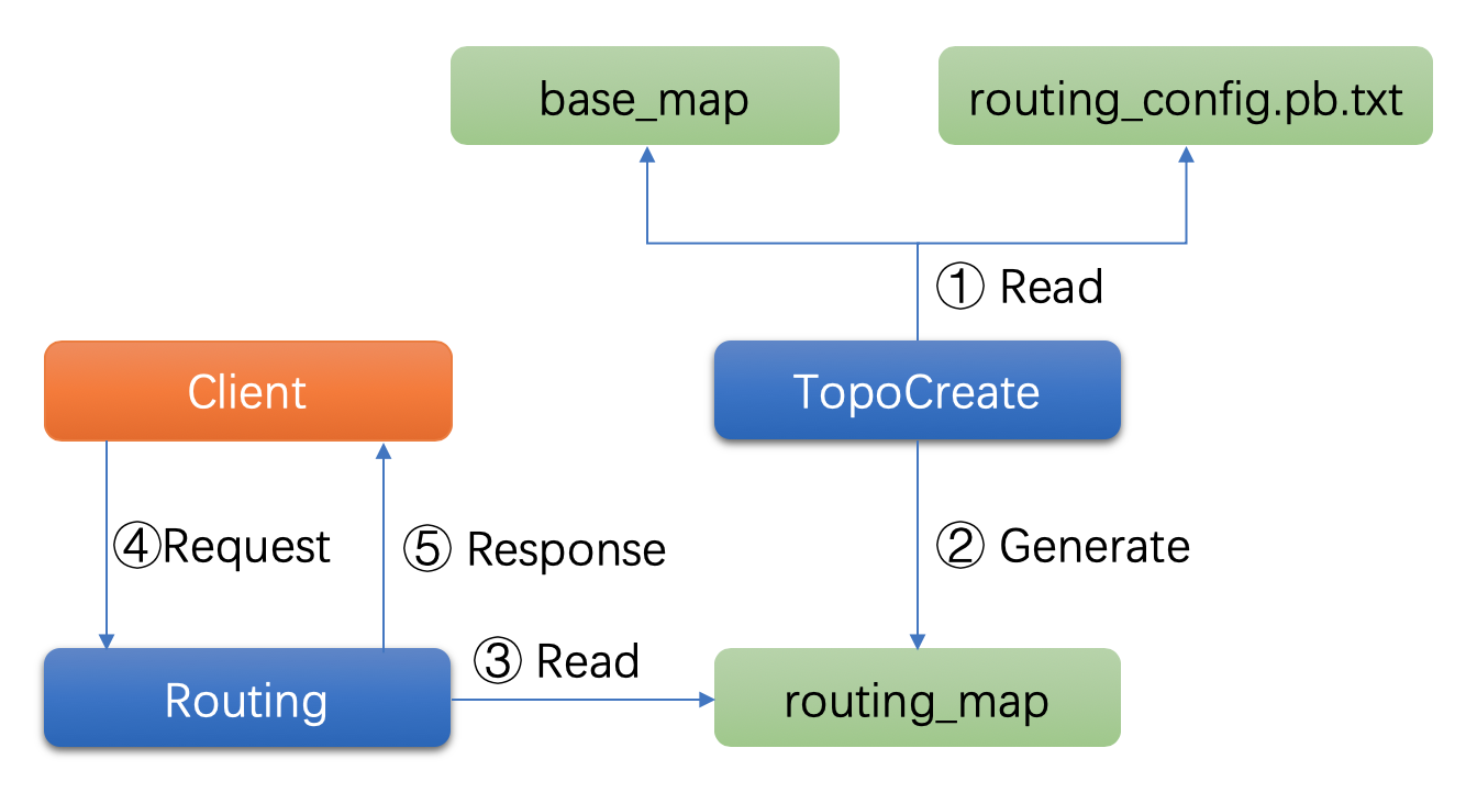
The logic here is very simple, that is, first read the information in the configuration file into RoutingConfig, and then generate the Topo map required by the Routing module according to the HD map file through GraphCreator.
The adjustment of the value in the configuration file (routing_config.pb.txt) will affect the calculation cost of the Topo map generated here, and these costs will be considered when the Routing module actually performs route search, which will affect the final navigation calculation result. The whole process is shown in the following figure:
Routing module initialization
The Routing module is initialized by the Init method. During initialization, the Navigator object will be created and the map will be loaded. The relevant codes are as follows:
apollo::common::Status Routing::Init() {
  const auto routing_map_file = apollo::hdmap::RoutingMapFile();
  AINFO << "Use routing topology graph path: " << routing_map_file;
  navigator_ptr_.reset(new Navigator(routing_map_file));
  CHECK(common::util::GetProtoFromFile(FLAGS_routing_conf_file, &routing_conf_))
      << "Unable to load routing conf file: " + FLAGS_routing_conf_file;

  AINFO << "Conf file: " << FLAGS_routing_conf_file << " is loaded.";

  hdmap_ = apollo::hdmap::HDMapUtil::BaseMapPtr();
  CHECK(hdmap_) << "Failed to load map file:" << apollo::hdmap::BaseMapFile();

  return apollo::common::Status::OK();
}
Initialization of Navigator
The internal of Routing will search the path through the Navigator. Because you need to search the path, Navigator needs a complete Topo map. In its constructor, the loading of the Topo map is completed.
Relevant codes are as follows:
Navigator::Navigator(const std::string& topo_file_path) {
  Graph graph;
  if (!common::util::GetProtoFromFile(topo_file_path, &graph)) {
    AERROR << "Failed to read topology graph from " << topo_file_path;
    return;
  }

  graph_.reset(new TopoGraph());
  if (!graph_->LoadGraph(graph)) {
    AINFO << "Failed to init navigator graph failed! File path: "
          << topo_file_path;
    return;
  }
  black_list_generator_.reset(new BlackListRangeGenerator);
  result_generator_.reset(new ResultGenerator);
  is_ready_ = true;
  AINFO << "The navigator is ready.";
}
In addition to loading the map, the following two classes of objects are initialized:
- BlackListRangeGenerator: hides the map generator, which will be explained below.
- ResultGenerator: this object is used to generate search results after the search is completed.
Routing request
The interface for processing routing requests is as follows:
bool Routing::Process(const std::shared_ptr<RoutingRequest> &routing_request,
                      RoutingResponse* const routing_response);
This interface has only two very concise parameters: one is the input parameter routing that describes the request_ Request, an output parameter routing that contains the result_ response. They are all defined in the proto file.
RoutingRequest is defined as follows (we will see the structure of RoutingResponse later):
message LaneWaypoint {
  optional string id = 1;
  optional double s = 2;
  optional apollo.common.PointENU pose = 3;
}

message LaneSegment {
  optional string id = 1;
  optional double start_s = 2;
  optional double end_s = 3;
}

message RoutingRequest {
  optional apollo.common.Header header = 1;
  repeated LaneWaypoint waypoint = 2;
  repeated LaneSegment blacklisted_lane = 3;
  repeated string blacklisted_road = 4;
  optional bool broadcast = 5 [default = true];
  optional apollo.hdmap.ParkingSpace parking_space = 6;
}
The key message here is the following:
repeated LaneWaypoint waypoint = 2;
It describes the path point of a Routing request. repeated indicates that this data can appear multiple times. Therefore, the Routing module supports searching multiple path points at a time.
BlackMap
In some cases, the map may have missing information. In this case, the Routing module supports dynamic addition of some information. This logic is mainly completed through BlackListRangeGenerator and TopoRangeManager. Among them, the former provides an interface to add data, while the latter is responsible for storing these data.
The BlackListRangeGenerator class is defined as follows:
class BlackListRangeGenerator {
 public:
  BlackListRangeGenerator() = default;
  ~BlackListRangeGenerator() = default;

  void GenerateBlackMapFromRequest(const RoutingRequest& request,
                                   const TopoGraph* graph,
                                   TopoRangeManager* const range_manager) const;

  void AddBlackMapFromTerminal(const TopoNode* src_node,
                               const TopoNode* dest_node, double start_s,
                               double end_s,
                               TopoRangeManager* const range_manager) const;
};
As can be seen from this definition, it provides two interfaces to add data:
- GenerateBlackMapFromRequest: added from the data contained in the RoutingRequest.
- AddBlackMapFromTerminal: adds data from the terminal.
Both interfaces will finally add data through the TopoRangeManager::Add interface. The method code is as follows:
void TopoRangeManager::Add(const TopoNode* node, double start_s, double end_s) {
    NodeSRange range(start_s, end_s);
    range_map_[node].push_back(range);
}
The data in the TopOrange manager will eventually be used by the ResultGenerator when assembling search results.
Route search process
We mentioned navigator earlier. If you browse the code of this class, you will find. Navigator itself does not implement the path search algorithm. It only completes the search process of routing path with the help of other classes.
The related logic is in the Navigator::SearchRoute method. The method code is as follows:
bool Navigator::SearchRoute(const RoutingRequest& request,
                            RoutingResponse* const response) {
  if (!ShowRequestInfo(request, graph_.get())) { ①
    SetErrorCode(ErrorCode::ROUTING_ERROR_REQUEST,
                 "Error encountered when reading request point!",
                 response->mutable_status());
    return false;
  }

  if (!IsReady()) { ②
    SetErrorCode(ErrorCode::ROUTING_ERROR_NOT_READY, "Navigator is not ready!",
                 response->mutable_status());
    return false;
  }
  std::vector<const TopoNode*> way_nodes;
  std::vector<double> way_s;
  if (!Init(request, graph_.get(), &way_nodes, &way_s)) { ③
    SetErrorCode(ErrorCode::ROUTING_ERROR_NOT_READY,
                 "Failed to initialize navigator!", response->mutable_status());
    return false;
  }

  std::vector<NodeWithRange> result_nodes;
  if (!SearchRouteByStrategy(graph_.get(), way_nodes, way_s, &result_nodes)) { ④
    SetErrorCode(ErrorCode::ROUTING_ERROR_RESPONSE,
                 "Failed to find route with request!",
                 response->mutable_status());
    return false;
  }
  if (result_nodes.empty()) {
    SetErrorCode(ErrorCode::ROUTING_ERROR_RESPONSE, "Failed to result nodes!",
                 response->mutable_status());
    return false;
  }
  result_nodes.front().SetStartS(request.waypoint().begin()->s());
  result_nodes.back().SetEndS(request.waypoint().rbegin()->s());

  if (!result_generator_->GeneratePassageRegion( ⑤
          graph_->MapVersion(), request, result_nodes, topo_range_manager_,
          response)) {
    SetErrorCode(ErrorCode::ROUTING_ERROR_RESPONSE,
                 "Failed to generate passage regions based on result lanes",
                 response->mutable_status());
    return false;
  }
  SetErrorCode(ErrorCode::OK, "Success!", response->mutable_status());

  PrintDebugData(result_nodes);
  return true;
}
Although this code is long, the main logic is clear, mainly including the following steps:
- Check the request parameters;
- Judge whether it is ready;
- Parameters required for initialization request;
- Execute the search algorithm;
- Assemble search results;
The search results are assembled through the ResultGenerator with the help of the search results STD:: vector < nodewithrange > and TopoRangeManager.
As mentioned earlier, the RoutingResponse type of search results is also defined in the proto file, and its contents are as follows:
message RoutingResponse {
  optional apollo.common.Header header = 1;
  repeated RoadSegment road = 2;
  optional Measurement measurement = 3;
  optional RoutingRequest routing_request = 4;
  optional bytes map_version = 5;
  optional apollo.common.StatusPb status = 6;
}
AStarStrategy
The fourth step of the Navigator::SearchRoute method calls the SearchRouteByStrategy method of the class itself. In this method, the path search will be completed with the help of AStarStrategy.
AStarStrategy class is a subclass of abstract class Strategy. The structure of these two classes is shown in the following figure:
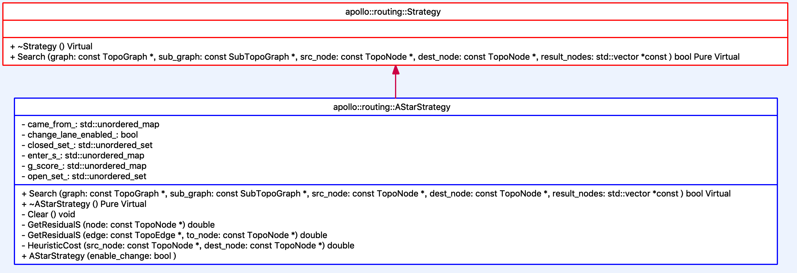
Obviously, this is Strategy design pattern Application of. The purpose of defining the Strategy base class is to easily implement another algorithm to replace the original A * algorithm in the future.
From the name of the AStarStrategy class, we can see that the implementation of this class searches the path through the A * algorithm. We have explained the A * algorithm in detail in another article( A * algorithm for path planning )Therefore, it will not be repeated here.
For readers who do not understand the A * algorithm, you can read that article first. Here is just A description of the key concepts of A * implementation in Apollo.
AStarStrategy is provided by a_star_strategy.cc implementation, the corresponding header file is a_star_strategy.h. Its class is defined as follows:
class AStarStrategy : public Strategy {
 public:
  explicit AStarStrategy(bool enable_change);
  ~AStarStrategy() = default;

  virtual bool Search(const TopoGraph* graph, const SubTopoGraph* sub_graph,
                      const TopoNode* src_node, const TopoNode* dest_node,
                      std::vector<NodeWithRange>* const result_nodes);

 private:
  void Clear();
  double HeuristicCost(const TopoNode* src_node, const TopoNode* dest_node);
  double GetResidualS(const TopoNode* node);
  double GetResidualS(const TopoEdge* edge, const TopoNode* to_node);

 private:
  bool change_lane_enabled_;
  std::unordered_set<const TopoNode*> open_set_;
  std::unordered_set<const TopoNode*> closed_set_;
  std::unordered_map<const TopoNode*, const TopoNode*> came_from_;
  std::unordered_map<const TopoNode*, double> g_score_;
  std::unordered_map<const TopoNode*, double> enter_s_;
};
The key to the implementation of a * algorithm is to calculate Cost, because Cost will affect the final search results. A key factor affecting Cost is the selection of heuristic function. Let's take a look at how it is implemented in Apollo.
- About cost: as mentioned earlier, the cost between nodes is stored in the Topo map in Proto format (the Topo map is generated by TopoCreator, and the cost value will be set according to the configuration file when it is generated), so it can be read directly here. The following function reads the cost between nodes:
double GetCostToNeighbor(const TopoEdge* edge) {
  return (edge->Cost() + edge->ToNode()->Cost());
}
The cost of each node can be calculated by the sum of the cost of adjacent nodes and the cost of edges connected to itself.
- About heuristic function: the A * algorithm in the Routing module uses the coordinate difference of TopoNode anchor as the heuristic function. The relevant codes are as follows:
double AStarStrategy::HeuristicCost(const TopoNode* src_node,
                                    const TopoNode* dest_node) {
  const auto& src_point = src_node->AnchorPoint();
  const auto& dest_point = dest_node->AnchorPoint();
  double distance = fabs(src_point.x() - dest_point.x()) +
                    fabs(src_point.y() - dest_point.y());
  return distance;
}
Routing search results
The search results of Routing are described by RoutingResponse. RoutingResponse and related structures are defined as follows:
message RoutingResponse {
  optional apollo.common.Header header = 1;
  repeated RoadSegment road = 2;
  optional Measurement measurement = 3;
  optional RoutingRequest routing_request = 4;

  optional bytes map_version = 5;
  optional apollo.common.StatusPb status = 6;
}

message RoadSegment {
  optional string id = 1;
  repeated Passage passage = 2;
}

message Passage {
  repeated LaneSegment segment = 1;
  optional bool can_exit = 2;
  optional ChangeLaneType change_lane_type = 3 [default = FORWARD];
}

message LaneSegment {
  optional string id = 1;
  optional double start_s = 2;
  optional double end_s = 3;
}

enum ChangeLaneType {
  FORWARD = 0;
  LEFT = 1;
  RIGHT = 2;
};

message Measurement {
  optional double distance = 1;
}
The attributes in RoutingResponse are described as follows:
| name | explain |
|---|---|
| header | Message header |
| road | Specific path information, the most important data |
| measurement | distance |
| routing_request | Original request |
| map_version | Map version |
| status | Status bit |
Obviously, the RoadSegment road here is the most important data. This data is actually a three-tier nested structure. Their descriptions are as follows:
- RoadSegment: describes a road. A road may contain several parallel passes.
- Passage: describes a passage, which is a driveable area directly connected without lane change. An access road may contain multiple lanes connected front and rear.
- LaneSegment: describes a lane. A lane is a section of a road. Autonomous vehicles will drive along the centerline of the lane as much as possible.
Cyber RT and module startup
Curious readers may find that at this point, we have not mentioned how the Routing module is started.
If you view the Routing module under the root directory BUILD File. You will find that the compiled product of the module is actually a dynamic library (so file), not an executable file.
So how does this module start? The answer is Cyber RT.
Apollo 3.5 completely abandoned ROS and used self-developed Cyber as the underlying communication and scheduling platform. Apollo Cyber RT system is a part of Apollo open source software platform layer. As a runtime computing framework, it is between real-time operating system (RTOS) and application modules. As a basic platform, Apollo Cyber RT supports smooth and efficient operation of all application modules.
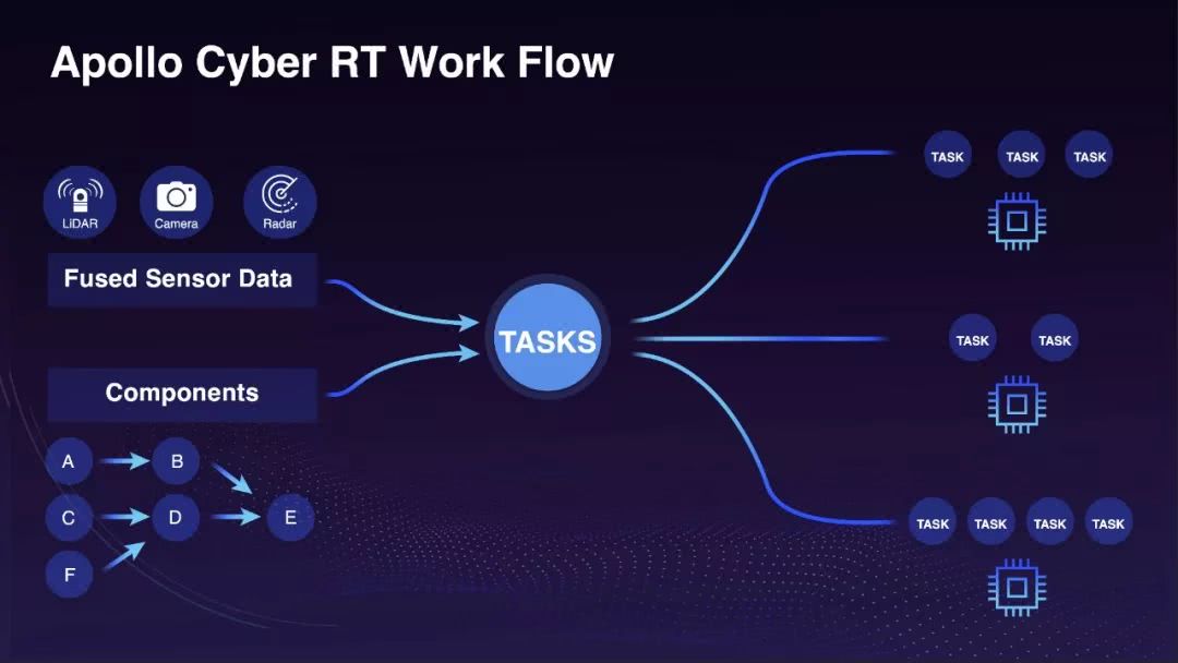
The workflow of Cyber RT is shown in the following figure:
In short, in Apollo 3.5, the startup of each module (including Localization, Perception, Prediction, Planning and Control) is handled by the cyberrt runtime.
If you browse the source code of the Routing module, you will find a dag file with the following contents:
# Define all coms in DAG streaming.
module_config {
    module_library : "/apollo/bazel-bin/modules/routing/librouting_component.so"
    components {
        class_name : "RoutingComponent"
        config {
            name : "routing"
            flag_file_path: "/apollo/modules/routing/conf/routing.conf"
            readers: [
                {
                    channel: "/apollo/routing_request"
                    qos_profile: {
                        depth : 10
                    }
                }
            ]
        }
    }
}
The core concept of Apollo Cyber RT framework is based on components, which have preset input and output. In fact, each component represents a dedicated algorithm module. The framework can generate a directed acyclic graph (DAG) based on all predefined components.
At runtime, the framework packages the fused sensor data and predefined components to form user level lightweight tasks. Then, the scheduler of the framework can dispatch these tasks according to resource availability and task priority.
We will not go further into this part. Interested readers can see the following two links:
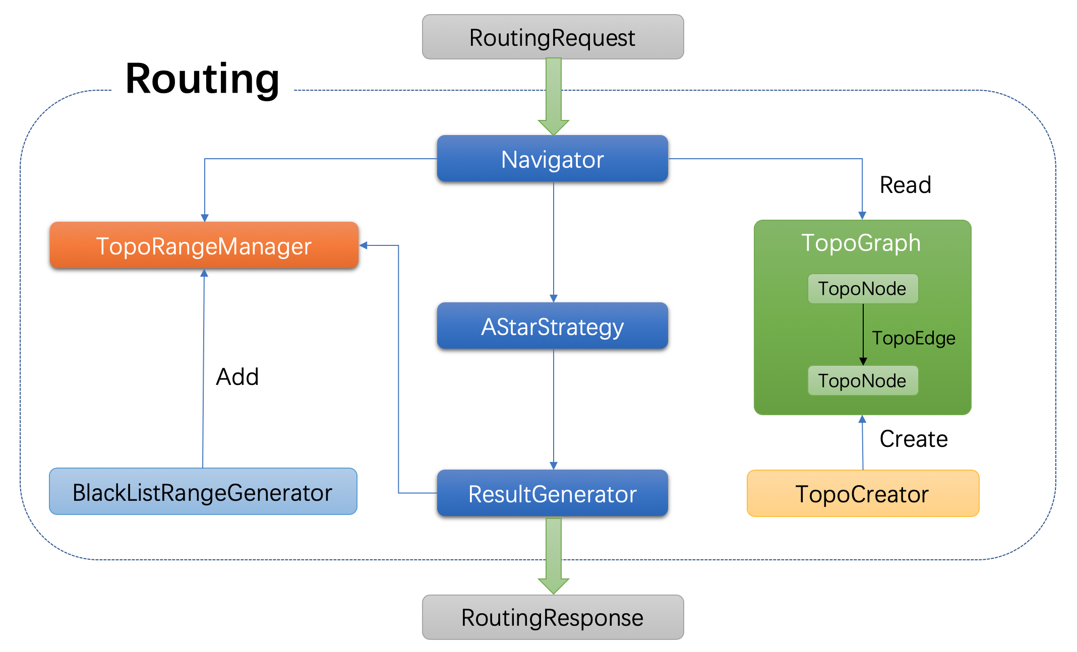
Routing module structure list
At the end of the paper, we describe the main components in the Routing module and their interaction through a diagram.
References and recommended readings
- ApolloAuto/apollo
- Detailed explanation of Apollo planning technology
- Analysis of startup process of each function module in Apollo 3.5
- Method of migrating Apollo project code to the Cyber RT framework (Apollo version 3.5 or above)
- Apollo Cyber RT framework
- Baidu Apollo EM Motion Planner
Original address: Analyzing the Routing module of Baidu Apollo by Paul's Bar