Application of ESP8266 based on punctual atom STM32F103ZET6
preface
The ATK-ESP8266 WIFI module of punctual atom is used in this test. Directly use the firmware provided by the official and use the AT command to configure the module and use it.
The module defaults to AT command status, and the analog baud rate is 115200 (8bit data bit, 1bit stop bit).
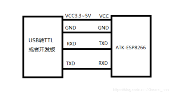
Hardware connection
Use USB to TTL mode (the computer needs to install CH340 driver) to connect ESP8266. The wiring diagram is as follows:
Introduction to Wifi module ESP8266
ESP8266 is a serial WIFI with low speed. It can not be used to transmit large capacity data such as images or videos. It is mainly used in occasions with less data transmission, such as temperature and humidity information, switching values of some sensors, etc.
ESP8266 is connected with MCU serial port. On the one hand, MCU can send AT command to ESP8266 through serial port, and ESP8266 will return a return value to MCU; On the other hand, when the mobile phone is connected with the ESP8266, the APP sends a command to the ESP8266 module through Wifi, and the ESP8266 receives and sends the command to the MCU through the serial port.
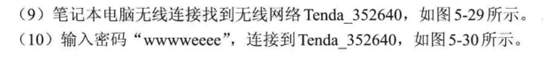
Advantages of ESP8266 module
Due to its fast speed, wide range, large amount of broadcast data and large power consumption, the disadvantage of WiFi has also been reversed with the introduction of low-power WiFi module. Therefore, low-power WiFi transparent module is gradually becoming the darling of low-power data transmission of the Internet of things.
The launch of WiFi transparent transmission module can quickly realize the intelligent transformation and upgrading of traditional products. It is applicable to smart wearable devices, smart homes, automotive electronics, leisure toys, security monitoring and other industries. It integrates existing solutions with the shortest development cycle to help customers quickly occupy the market and win the first opportunity.
WiFi transparent transmission module is different from the main control module. Its main control program is still in the appliance itself. The module is only used as a transmission channel without any processing of data. At the same time, it ensures the quality of transmission and reaches the final receiver intact.
Introduction to UDP & TCP protocol
① Brief introduction:
UDP is a broadcast communication mode, which transmits information to all devices that can receive its signal in the network. UDP communication does not have the strict sending and receiving inspection like TCP protocol. According to UDP protocol, the device only sends information, and I don't care whether the device at the other end receives it or not, and I still send mine. Therefore, UDP is a non blocking communication protocol.
Compared with UDP, TCP is a communication protocol with sending and receiving inspection measures, that is, sending and receiving double messages should be checked every interaction, so the efficiency is lower, but the security is improved. For example, compared with UDP, TCP has a buffer. When the other party does not respond to my message, I will constantly read the data from the TCP buffer and send it repeatedly until the other party responds successfully. This leads to the failure of one data interaction and the obstruction of the remaining data interaction, which is often referred to as "stuck".
② Differences between TCP and UDP protocols:
(1) both TCP and UDP belong to socket communication protocol. The former communicates in the form of 100 data streams, and the latter communicates in the form of data packets;
(2) TCP is a directed connection protocol and UDP is a undirected connection protocol;
⑶ when TCP Client and server establish a connection, they need three handshake protocols. UDP does not need handshake and sends data packets directly;
(4) TCP communication will not lose data, and UDP communication will lose data packets;
(5) in terms of communication reliability, TCP is more reliable than UDP;
(6) in terms of security, TCP security is higher than UDP;
(7) UDP adopts non blocking asynchronous communication mode, while TCP adopts blocking asynchronous communication mode.
Two modes of WIFI
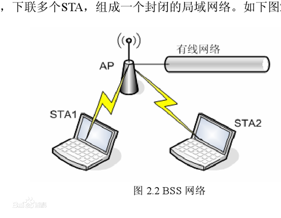
AP mode: Access Point provides wireless access service, allows other wireless devices to access and provides data access. General wireless routing / bridge works in this mode. AP and AP allow interconnection.
AP is the abbreviation of access point, An AP (such as a router) acts as a hub ", in a wired network, each device is a user. When there are only two users, we can connect them directly without intermediate media. However, if there are 10000 people in this network, the interconnection efficiency is very low and no possible. Therefore, we need to connect all end users in this wireless network to one node 1. Unified planning and management. This important point that plays a core role in the network is AP.
Sta mode: Station is similar to wireless terminal. Sta itself does not accept wireless access. It can connect to AP. Generally, the wireless network card works in this mode.
STA is the abbreviation of station. We can also see "station" from the name, which is translated into "terminal" in Chinese. Our network is composed of countless basic units, and our network cannot extend indefinitely. There must be an end point, which is our end-user devices (our smart phones, smart watches, PC s, etc.).
It should be mentioned here that "the whole large network is composed of many local area networks, but these local area networks are composed of many sub local area networks. These sub local area networks are the smallest unit network of the network, including one wireless connection point AP and several STA wireless terminals".
Several special parameters
① SSID(Service Set Identifier):SSID. Each wireless AP should have an identifier for user identification. SSID is the name used for user identification, that is, the wifi name we often talk about;
② BSSID: every network device has its physical address for identification. This thing is called MAC address. Generally, this thing has a default value that can be changed and has its fixed naming format. It is also an identifier for device identification. The BSSID is for devices. For STA devices, the MAC address of the AP access point is the BSSID;
③ ESSID is a relatively abstract concept. It is actually the same as SSID (a string of characters in essence). However, if several wireless routers are called this name, we will expand this SSID. Therefore, the common name of these wireless routers is ESSID. For example, a company has a large area and installed several wireless access points (AP S or wireless routers). Employees of the company only need to know one SSID to access the wireless network anywhere in the company. BSSID is actually the MAC address of each wireless access point. SSID is unchanged when employees move within the company. But BSSID is constantly changing as you switch to different wireless access points;
④ RSSI: the signal strength scanned to the AP station through STA;
⑤ IP: the essential difference between IP and MAC is that MAC is used to distinguish various devices in a LAN, and IP is used to distinguish different LANs in a wide area network (Network). For example, the IP address of each device in a LAN with a router as AP and several WIFI devices as STA is the same. We generally refer to private IP in ESP8266. The biggest difference between private IP and public IP is that in the current network, IP address is divided into public IP address and private IP address. Public IP is the IP address used in the Internet, while private IP address is the IP address used in the LAN. A private IP address is a reserved IP address. It is only used in the LAN and cannot be used on the Internet, that is, ESP8266 cannot provide Internet service;
⑥ ID number of TCP client and port number of TCP server: in the sub LAN, the ID number of TCP client makes it different from other TCP clients in the network. Similarly, the port number of TCP server makes it different from other TCP servers in the network.
Server VS client
When using TCP communication to establish a connection, the Client server mode is adopted. This mode is often called master-slave architecture, which is referred to as C/S structure for short. It belongs to a network communication architecture, which distinguishes the two sides of communication as Client and server. Only the Client can actively connect to the server, not the server. In fact, it's understandable. If my server sends a connection request to each Client, is this still called low power consumption? Low power consumption means "supply on demand". Therefore, low power consumption requires us to "provide services according to the needs of clients" rather than "actively go to each Client to ask whether services need to be provided".
Characteristics of the server: passive role, waiting for the connection request from the client, processing the request and returning the result;
Characteristics of the client: active role, sending connection request and waiting for the response of the server.
In fact, to put it bluntly, the server uniformly distributes and manages the data received from the client. For example, there are two kinds of QQ, one is the server transfer message and the other is the P2P message. For the relay message, if it is only a separate message, when the client connects to the server, the server will process the client message, such as arranging INDEX. Then client ID01 is ready to send a message to client ID02. Then the protocol should include the client object and message content. Then the client ID01 sends this request message to the server. When the server receives the request from ID01 to send a message to ID02 and agrees, the server sends the message content to the corresponding target, that is, the client ID02.. For mass messaging, you only need to change to server broadcast messages instead of specifying the target when sending messages. That is, for the server side that receives the message request, the server will broadcast and send messages to all connected clients.
Transparent transmission mode
① What is the transparent mode?
Transparent transmission, also known as transparent transmission, is specifically "input is output". For example, the characters input from the serial port of the WiFi module will be transmitted to the server. The data does not change, and the conversion between different protocols (such as serial port to WiFi) is completed by the module. The user does not need to care about the internal specific implementation, so the module is "transparent" to the user and does not seem to exist "because the intermediate implementation principle can be ignored". This is like mailing letters. Letters may reach you by bike, car, train, plane and other combined transportation methods, but you don't have to care about what they have experienced.
Note: ATK_ESP8266 module supports transparent transmission mode only in TCP Client and UDP.
② What's the use of transparent mode?
Transparent transmission is generally used to read remote serial port data. For example, every Internet user in the Internet cafe must brush his ID card to surf the Internet, but the ID card database cannot be placed in each Internet cafe. So the serial data of the card reader is transmitted back to the Public Security Bureau through the transparent transmission, and the ID number is compared to the platform of the Public Security Bureau.
Three working modes of ESP8266
ESP8266 supports three working modes: STA / AP / STA+AP:
① STA mode: the ESP8266 module is connected to the Internet through the router, and the remote control of the equipment can be realized through the Internet. Similar to wireless network card;
② AP mode: as a hotspot, ESP8266 module can realize the direct communication between mobile phones or other networked devices and the module through WIFI to realize LAN wireless control. Similar to routing or bridge;
③ STA+AP mode: both modes are supported.
Generally speaking, STA mode is a networking device that needs to be connected to other wireless routers through wifi. AP mode is a wireless router, and other networked devices can access through wifi.
Collocation of WIFI working mode and subordination in communication network
Multi connection mode: a TCP client can send information to multiple TCP servers.
① Request and communication:
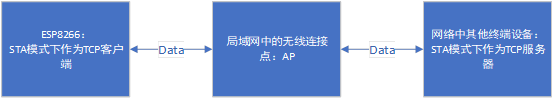
STA mode means that the module directly connects to the AP (mobile hotspot or router) and enters the LAN to communicate with other wireless devices. Since ESP8266 acts as a TCP client in STA mode, ESP8266 acts as a client in the LAN and other devices act as a server.
The process of establishing connection between two terminals (WIFI device in STA working mode):
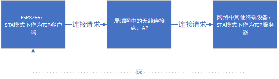
② Important parameters when establishing connection:
(1) configure SSID and PassWord:
This is a necessity for AP connecting wireless connection points in LAN. SSID and PassWord are inherent attributes of AP and important means of distribution network:
1. SSID technology can divide a WLAN into several sub networks requiring different authentication;
2. Each sub network requires independent authentication, i.e. PassWord password. Only authenticated users can enter the corresponding sub network to prevent unauthorized users from entering the network.
③ Configuration process of AT instruction:
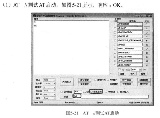
(1) test whether ESP8266 can receive AT command:
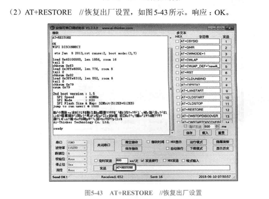
(2) restore the factory setting of ESP8266:
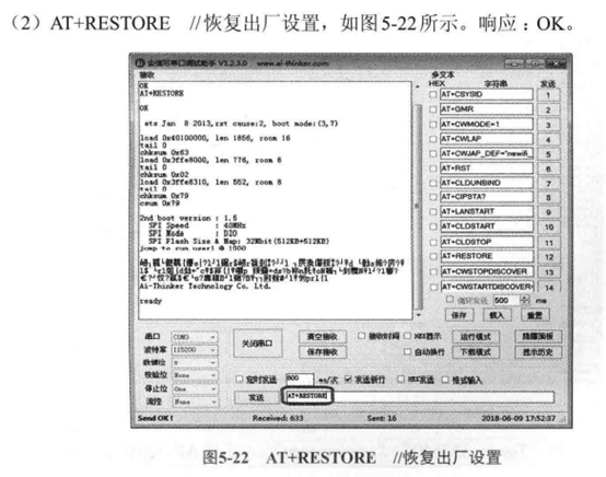
Here, it usually takes about 3s to restore the factory settings.
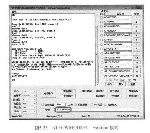
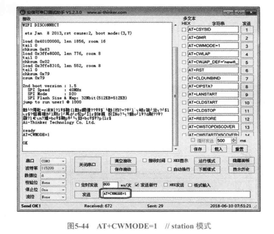
⑶ configure ESP8266 as STA mode:
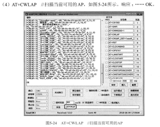
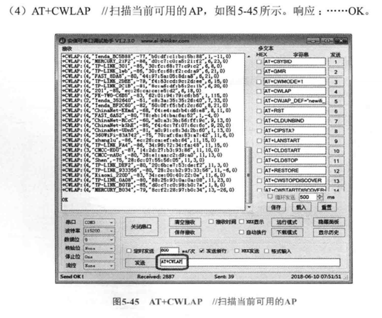
(4) current AP scan available:
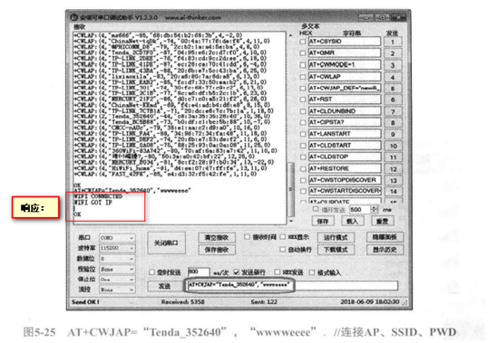
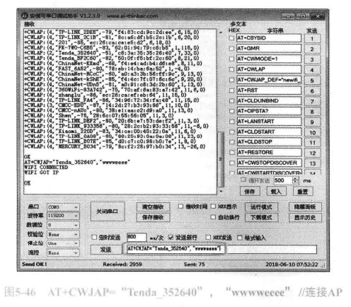
(5) connect the designated AP:
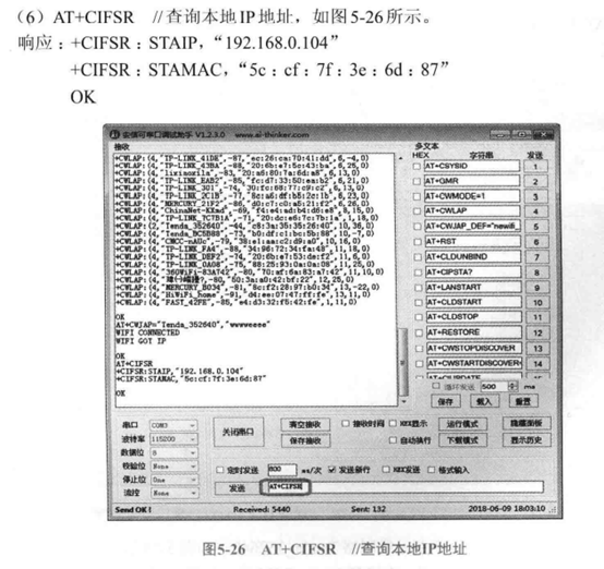
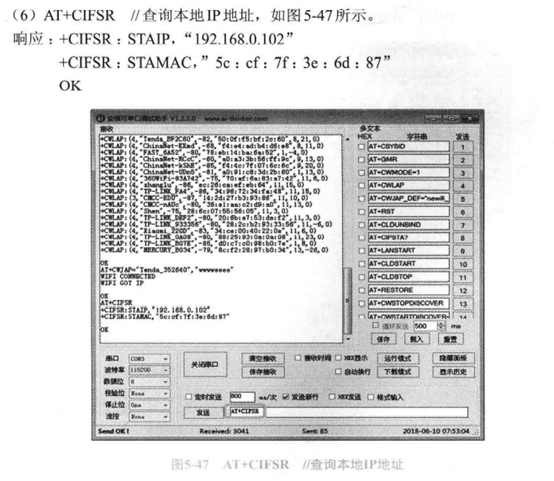
(6) query local IP:
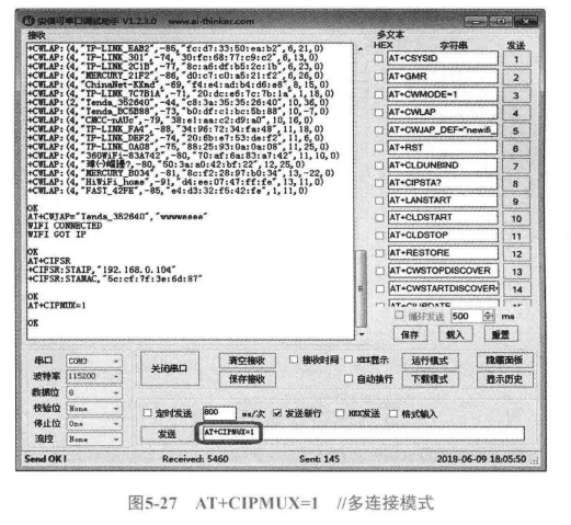
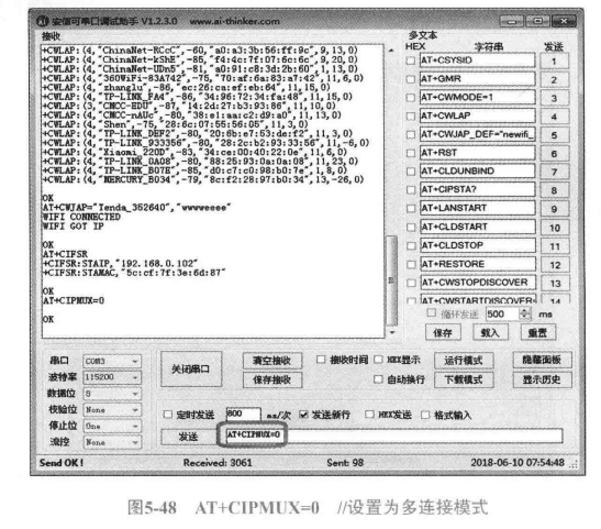
(7) set to multi connection mode:
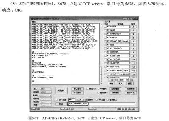
(8) after configuring the working mode of WIFI, configure the master-slave relationship and port name of ESP8266 in TCP protocol:
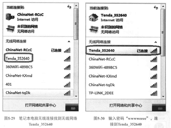
(9) after setting the working mode and TCP dependency of ESP8266, it is time to configure PC / mobile terminal:
First of all, we need to connect the ESP8266 and PC side computers, which are two STA devices, to an AP, that is, the same router:
It must be noted here that the AP in this wireless network is served by the WIFI router named "Tenda_352640". This AP is not ESP8266, but a WIFI device in STA working mode.
Secondly, we need to open the network debugging assistant to configure the TCP mode of PC-side computer devices:
Select TCP Client mode and set the TCP server port to be connected to 5678 (the working port of esp8266 under TCP protocol)
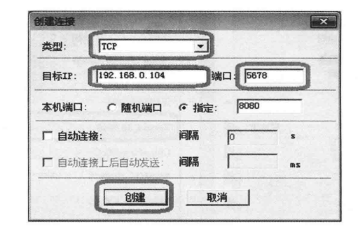
We only pay attention to the TCP port number when the PC is a TCP server.
Finally, after the connection is successful, ESP8266 will return "ID numbers of all TCP clients working in STA mode" to the serial port debugging assistant:
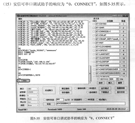
Since there is only one STA terminal device (PC computer) connected to this "AP wireless network connection node" as a TCP client, only the ID number of the TCP client of ESP8266 is displayed here: 0.
(10) let's think about it: from the perspective of the TCP client, we know the port number of the TCP server, and we can configure the TCP client to send data to the designated TCP server. But from the perspective of the TCP server, is the data received by the TCP server sent by the designated TCP client? The ID number of TCP client can tell us the answer.
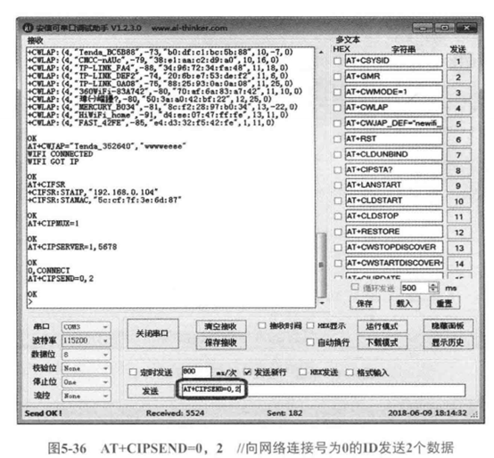
This means that the PC receives 2 bytes of data transmitted by the ID0 client (ESP8266). Here, the ESP8266 is configured to receive only 2 bytes of data transmitted from the PC.
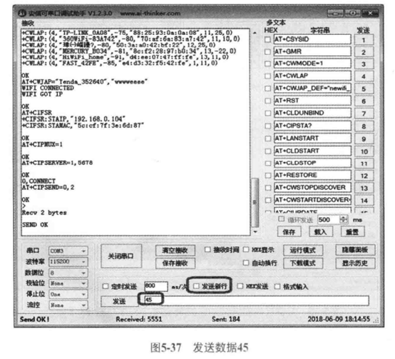
(11) you can start sending data at this time, because we open the transparent transmission mode under the STA working mode, so we only need to send data (two data in total). Note: there is no need to click "send new line":
(12) when we finish transmitting data, we need to exit the transparent transmission mode:
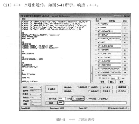
Remember here that you do not need to click "send new line".
Module TCP Client transparent transmission mode (single connection mode)
Transparent transmission mode: it is a single connection mode, which can realize the data transmission between a TCP server and a TCP Client. Note: ATK_ESP8266 module supports transparent transmission mode only in TCP Client and UDP.
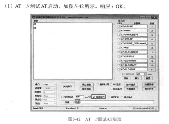
(1) test whether the AT command is normal:
(2) restore the factory setting of ESP8266:
Here, it usually takes about 3s to restore the factory settings.
⑶ configure ESP8266 as STA mode:
(4) scanning the currently available AP is equivalent to finding the available LAN of the location:
(5) connect available LAN:
This step is to connect the ESP8266 to an available LAN.
(6) query local IP:
The two working modes of STA and AP correspond to two different MAC and IP addresses.
(7) since the transparent transmission mode is single connection mode, we turn off the multi connection mode:
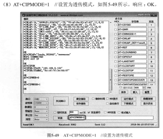
(8) set to transparent transmission mode:
Since ESP8266 works in STA mode and is in transparent transmission mode, we can see that ESP8266 is "TCP client in STA mode" in the sub LAN at this time.
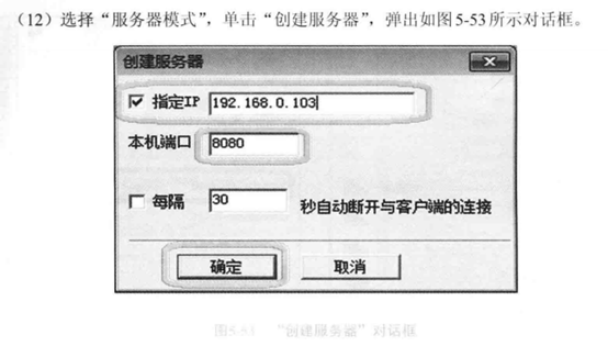
(9) configure the PC as a TCP server, set the TCP port number of the PC and specify the IP address:
(10) configure the IP address and TCP port number of the TCP server to which ESP8266 is connected:
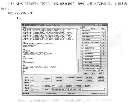
In this way, it can realize fast terminal to terminal fast connection. Just like our Bluetooth headset, it can automatically pair a specific mobile phone when turned on.
(11) start sending data:
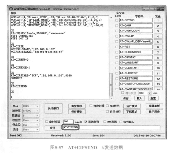
We need to pay attention to:
Key program analysis (punctual atomic routine)
Serial port configuration
① Serial port initialization
(1) procedure example:
//Initialize IO # serial port 3
//pclk1:PCLK1 clock frequency (Mhz)
//bound: baud rate
void usart3_init(u32 bound)
{

 NVIC_InitTypeDef NVIC_InitStructure;
 GPIO_InitTypeDef GPIO_InitStructure;
 USART_InitTypeDef USART_InitStructure;

 RCC_APB2PeriphClockCmd(RCC_APB2Periph_GPIOB, ENABLE); //GPIOB clock
 RCC_APB1PeriphClockCmd(RCC_APB1Periph_USART3,ENABLE); //Serial port 3 clock enable

  USART_DeInit(USART3);  //Reset serial port 3

    //USART3_TX   PB10
    GPIO_InitStructure.GPIO_Pin = GPIO_Pin_10; //PB10
    GPIO_InitStructure.GPIO_Speed = GPIO_Speed_50MHz;
    GPIO_InitStructure.GPIO_Mode = GPIO_Mode_AF_PP; //Multiplex push-pull output
    GPIO_Init(GPIOB, &GPIO_InitStructure); //Initialize PB10

    //USART3_RX   PB11
    GPIO_InitStructure.GPIO_Pin = GPIO_Pin_11;
    GPIO_InitStructure.GPIO_Mode = GPIO_Mode_IN_FLOATING;//Floating input
    GPIO_Init(GPIOB, &GPIO_InitStructure);  //Initialize PB11

 USART_InitStructure.USART_BaudRate = bound;//Baud rate is generally set to 9600;
 USART_InitStructure.USART_WordLength = USART_WordLength_8b;//The word length is in 8-bit data format
 USART_InitStructure.USART_StopBits = USART_StopBits_1;//A stop bit
 USART_InitStructure.USART_Parity = USART_Parity_No;//No parity bit
 USART_InitStructure.USART_HardwareFlowControl = USART_HardwareFlowControl_None;//No hardware data flow control
 USART_InitStructure.USART_Mode = USART_Mode_Rx | USART_Mode_Tx; //Transceiver mode

 USART_Init(USART3, &USART_InitStructure); //Initialize serial port 3

 USART_Cmd(USART3, ENABLE);                    //Enable serial port

 //Enable receive interrupt
    USART_ITConfig(USART3, USART_IT_RXNE, ENABLE);//Open interrupt

 //Set interrupt priority
 NVIC_InitStructure.NVIC_IRQChannel = USART3_IRQn;
 NVIC_InitStructure.NVIC_IRQChannelPreemptionPriority=2 ;//Preemption priority 3
 NVIC_InitStructure.NVIC_IRQChannelSubPriority = 3;  //Sub priority 3
 NVIC_InitStructure.NVIC_IRQChannelCmd = ENABLE;   //IRQ channel enable
 NVIC_Init(&NVIC_InitStructure); //Initializes the VIC register according to the specified parameters

 TIM7_Int_Init(1000-1,7200-1);  //TIM7 10ms trigger interrupt
 USART3_RX_STA=0;  //Clear
 TIM_Cmd(TIM7,DISABLE);   //Turn off timer 7

}
Note: when USART3 receives data, it triggers an interrupt to execute the interrupt service function.
② Interrupt service function of serial port 3
(1) program example
//Serial port receiving buffer
u8 USART3_RX_BUF[USART3_MAX_RECV_LEN];     //Receive buffer, maximum USART3_MAX_RECV_LEN bytes
u8  USART3_TX_BUF[USART3_MAX_SEND_LEN];    //Send buffer, maximum USART3_MAX_SEND_LEN byte

//[15] : 0: no data received; 1: The buffer for receiving data is full of data
//[14:0]: received data length
vu16 USART3_RX_STA=0;


//Note: determine whether it is continuous data at one time by judging that the time difference between receiving two consecutive characters is no more than 10ms
/*Functions implemented by interrupt service function:
If the receiving interval of two characters exceeds 10ms, it is considered that it is not a continuous data That is, if no data is received for more than 10ms, it means that the reception is completed*/
void USART3_IRQHandler(void)
{
 u8 res;
 if(USART_GetITStatus(USART3, USART_IT_RXNE) != RESET)//Data received
 {
  res =USART_ReceiveData(USART3);
  if((USART3_RX_STA&(1<<15))==0)//If a batch of received data has not been processed, no other data will be received
  {
   if(USART3_RX_STA<USART3_MAX_RECV_LEN) //You can also receive data
   {
    TIM_SetCounter(TIM7,0);//Counter clear
    if(USART3_RX_STA==0)     //Interrupt of enable timer 7
    {
     TIM_Cmd(TIM7,ENABLE);//Enable timer 7
    }
    USART3_RX_BUF[USART3_RX_STA++]=res; //Record the received value
   }
     else
   {
    USART3_RX_STA|=1<<15;    //Force mark reception complete
   }
  }
 }
}
(2) key parameters:
Receive buffer status parameters:
| USART3_RX_STA | 15 | 14:0 |
| meaning | Is the accept buffer full | The actual length of data received by the receive buffer |
Length of receive buffer & send buffer:
| Predefined name | value |
| USART3_MAX_RECV_LEN | 600 |
| USART3_MAX_SEND_LEN | 600 |
(3) procedure execution process:
1. When ESP8266 sends data to the development board, usart3 of the development board_ RX pin will accept data and trigger interrupt;
2. View usart3_ RX_ Whether the 15th bit of sta is 1. If it is 1, it indicates that the receiving buffer is full, and then it indicates that the last loaded data has not been processed; If it is 0, continue to load the data into the buffer;
3. Remove usart3 until it is full_ RX_ The 15th position of sta is 1;
The meaning of this function is to store "all the information returned to the serial port by ESP8266 every time an AT instruction is sent" into the receiving buffer.
③ Serial port printing function
(1) code example:
//Serial port 3,printf function
//Ensure that the data sent at one time does not exceed USART3_MAX_SEND_LEN byte
void u3_printf(char* fmt,...)
{
 u16 i,j;
 va_list ap;
 va_start(ap,fmt);
 vsprintf((char*)USART3_TX_BUF,fmt,ap);
 va_end(ap);
 i=strlen((const char*)USART3_TX_BUF);  //Length of data sent this time
 for(j=0;j<i;j++)       //Send data circularly
 {
   while(USART_GetFlagStatus(USART3,USART_FLAG_TC)==RESET); //Send circularly until sending is completed
  USART_SendData(USART3,USART3_TX_BUF[j]);
 }
}
Note: u8 * here represents char *
(2) procedure execution process:
1. Load the input string into the transmission buffer using vsprintf function;
2. Send circularly until sending is completed
Functions used with timer and serial port
(1) timer configuration function
//The general timer 7 interrupts initialization. Here, the clock selection is twice that of APB1
//arr: automatic reassembly value # psc: clock pre division frequency
//Calculation method of timer overflow time: Tout=((arr+1)*(psc+1))/Ft · us
//Ft = working frequency of timer, unit: Mhz
//General timer interrupt initialization
void TIM7_Int_Init(u16 arr,u16 psc)
{
 NVIC_InitTypeDef NVIC_InitStructure;
 TIM_TimeBaseInitTypeDef  TIM_TimeBaseStructure;

 RCC_APB1PeriphClockCmd(RCC_APB1Periph_TIM7, ENABLE);//TIM7 clock enable

 //Timer TIM7 initialization
 TIM_TimeBaseStructure.TIM_Period = arr; //Sets the value of the auto reload register cycle of the load activity at the next update event
 TIM_TimeBaseStructure.TIM_Prescaler =psc; //Sets the prescaled value used as the divisor of TIMx clock frequency
 TIM_TimeBaseStructure.TIM_ClockDivision = TIM_CKD_DIV1; //Set clock division: TDTS = Tck_tim
 TIM_TimeBaseStructure.TIM_CounterMode = TIM_CounterMode_Up;  //TIM up count mode
 TIM_TimeBaseInit(TIM7, &TIM_TimeBaseStructure); //Initializes the time base unit of TIMx according to the specified parameters

 TIM_ITConfig(TIM7,TIM_IT_Update,ENABLE ); //Enables the specified TIM7 interrupt and allows the update interrupt

 TIM_Cmd(TIM7,ENABLE);//Turn on timer 7

 NVIC_InitStructure.NVIC_IRQChannel = TIM7_IRQn;
 NVIC_InitStructure.NVIC_IRQChannelPreemptionPriority=0 ;//Preemption priority 0
 NVIC_InitStructure.NVIC_IRQChannelSubPriority = 2;  //Sub priority 2
 NVIC_InitStructure.NVIC_IRQChannelCmd = ENABLE;   //IRQ channel enable
 NVIC_Init(&NVIC_InitStructure); //Initializes the VIC register according to the specified parameters

}
Note: TIM7 turns on timer update interrupt.
(2) TIM7 interrupt service function
extern vu16 USART3_RX_STA;

//Timer 7 interrupt service program
void TIM7_IRQHandler(void)
{
 if (TIM_GetITStatus(TIM7, TIM_IT_Update) != RESET)//Is the update interrupted
 {
  USART3_RX_STA|=1<<15; //Mark receipt complete
  TIM_ClearITPendingBit(TIM7, TIM_IT_Update  );  //Clear TIM7 update interrupt flag
  TIM_Cmd(TIM7, DISABLE);  //Turn off TIM7
 }
}
We remember that we mentioned earlier: if the receiving interval of two characters exceeds 10ms, it is considered that it is not a continuous data That is, it is not received for more than 10ms. Here, the matching process of USART3-TIM7 is as follows:
1. When the signal is transmitted to USART3, if the last received data processing is completed, start TIM7 timer update interrupt for 10ms;
2. When the data transmission lasts for 10ms, we cut off the data transmission. We think 10ms is the maximum duration of data transmission. At this time, we will use usart3_ RX_ The 15th position 1 of sta means that the transmission is completed successfully.
Note: there are two ways to set the transmission successful completion flag: first, the string returned to the serial port is too long and exceeds the maximum length specified in the receiving buffer. At this time, it is forced to stop receiving more characters; Second, the return time is more than 10ms. We think that the information return has ended at this time, and the mark is forced to be placed at position 1.
Several important instruction transfer functions based on serial port information transmission
① Instruction transfer function
(1) code example:
//Function: send command to ESP8266
//cmd: command string sent; ack: the expected response result. If it is empty, it means there is no need to wait for a response; waittime: waiting time (unit: 10ms)
//Return value: 0, the transmission is successful (the expected response result is obtained); 1. Sending failed
u8 esp8266_send_cmd(u8 *cmd,u8 *ack,u16 waittime)
{
 u8 res=0;
 USART3_RX_STA=0;
 u3_printf("%s\r\n",cmd); //dispatch orders
 if(ack&&waittime)  //Need to wait for response
 {
  while(--waittime) //Wait for countdown
  {
   delay_ms(10);
   if(USART3_RX_STA&0X8000)//Expected response result received
   {
    if(esp8266_check_cmd(ack))
    {
     printf("ack:%s\r\n",(u8*)ack);
     break;//Get valid data
    }
    USART3_RX_STA=0;
   }
  }
  if(waittime==0)res=1;
 }
 return res;
}
(2) parameter description
| Parameter name | Parameter data type | meaning |
| cmd | char* | AT instruction |
| ack | char* | We expect the response result corresponding to the AT instruction |
| waittime | short int | Maximum polling wait time |
(3) function execution process
1. When we resend an instruction, we need to initialize: set the initial number of received data in the receiving buffer and the state of the receiving buffer to zero (USART3_RX_STA=0);
2. When we use encapsulated us_ When the printf function sends data through the serial port, the returned data will trigger the serial port reception interrupt, so as to make the data transmission complete flag position 1, that is, usart3_ RX_ The 15th position 1 of sta;
3. When we cannot receive the response we want, we will not receive any data, that is, USART3_RX_STA set to 0
② "Check whether the received response is the function we want"
(1) code example:
//After sending the command, ESP8266 detects the received response
//str: expected response
//Return value: 0, the expected response result is not obtained; Other, the position where the response result is expected (the position of str)
u8* esp8266_check_cmd(u8 *str)
{
 char *strx=0;
 if(USART3_RX_STA&0X8000)  //Received data once
 {
  USART3_RX_BUF[USART3_RX_STA&0X7FFF]=0;//Add Terminator
  strx=strstr((const char*)USART3_RX_BUF,(const char*)str);
 }
 return (u8*)strx;
}
(2) parameter description:
| Parameter name | Parameter data type | meaning |
| Return value strx | char* | The first address of the response string we expect |
| Enter the value str | char* | 0(NULL): the expected response result is not obtained; Address: the location where the response result is expected (the location of str) |
(3) function execution process:
We know that a string ends with '\ 0', otherwise the string we read out in memory will have some garbled code. Therefore, we need to add the '\ 0' string terminator after the last non '\ 0' character element in the buffer. Then, we use string The strstr function in the H header file finds the response string we want in the receive buffer and returns the address where the first character of the response string appears in the receive buffer.
③ Function to send data to ESP8266
1. Code example:
//Send data to ESP8266
//cmd: command string sent; waittime: waiting time (unit: 10ms)
//Return value: the verification code returned by the server after sending data
u8* esp8266_send_data(u8 *cmd,u16 waittime)
{
 char temp[5];
 char *ack=temp;
 USART3_RX_STA=0;
 u3_printf("%s",cmd); //When sending a command, remember "there is no line feed ('\ n\r') sent here."“
 if(waittime)  //Need to wait for response
 {
  while(--waittime) //Wait for countdown
  {
   delay_ms(10);
   if(USART3_RX_STA&0X8000)//Expected response result received
   {
    USART3_RX_BUF[USART3_RX_STA&0X7FFF]=0;//Add Terminator
    ack=(char*)USART3_RX_BUF;
    printf("ack:%s\r\n",(u8*)ack);
    USART3_RX_STA=0;
    break;//Get valid data
   }
  }
 }
 return (u8*)ack;
}
2. Parameter Description:
| Parameter name | Parameter data type | meaning |
| cmd | char* | AT instruction |
| waittime | short int | Maximum polling wait time |
3. Function execution process:
When we use us_ After printf sends data to the serial port, the returned serial port data will trigger USART_RX reception is interrupted, and the returned data will be continuously loaded into the receiving buffer. When the transmission of the returned information is completed, the transmission completion flag bit will be set to 1. At this time, we need to add the '\ 0' string end flag after the last non '\ 0' character. Then print the string of the receiving buffer to the screen, and then zero the index of the initial receiving buffer and the status flag of the receiving buffer, that is, USART3_RX_STA is set to zero.
4. Compare the difference between "function for sending command":
The function used to send the command needs to check whether the returned string is what we want, that is, we need to check whether the instruction we send is right. In order to check whether the returned string is consistent with what we want, we have specially defined the function of "checking whether the returned string matches the expected string".
④ Function entering transparent mode
(1) function example:
//ESP8266 module and PC enter transparent transmission mode
void esp8266_start_trans(void)
{
 //Set working mode # 1: station mode # 2: AP mode # 3: compatible # AP+station mode
 esp8266_send_cmd("AT+CWMODE=1","OK",50);

 //Command to restart Wifi module
 esp8266_send_cmd("AT+RST","ready",20);

 delay_ms(1000);         //Delay for 3S and wait for successful restart
 delay_ms(1000);
 delay_ms(1000);
 delay_ms(1000);

 //Let the module connect to its own route
 while(esp8266_send_cmd("AT+CWJAP=\"xxxx\",\"xxxx\"","WIFI GOT IP",600));

 //=0: single connection mode = 1: multi connection mode
 esp8266_send_cmd("AT+CIPMUX=0","OK",20);

 //Establish a TCP connection. These four items respectively represent the ID number 0 ~ 4 to be connected, the connection type, the IP address of the remote server, and the port number of the remote server
 while(esp8266_send_cmd("AT+CIPSTART=\"TCP\",\"xxx.xxx.xxx.xxx\",xxxx","CONNECT",200));

 //Whether to turn on the transparent transmission mode or not ; 0: it means to turn off ; 1: it means to turn on the transparent transmission
 esp8266_send_cmd("AT+CIPMODE=1","OK",200);

 //In transparent transmission mode, you can send data directly after # starting to send data
 esp8266_send_cmd("AT+CIPSEND","OK",50);
}
(2) function execution process:
1. Configure ESP8266 as STA mode;
2. Restore ESP8266 to the factory setting and wait for 3s;
3. Wait to connect to the specified route;
4. Configure ESP8266 as single connection mode;
5. Turn on transparent transmission mode;
6. Send the instruction of "start data transmission".
After executing this function, you can send data.
⑤ Function to exit transparent mode
⑴. Code example:
//ESP8266 exits the transparent transmission mode} return value: 0, the exit is successful; 1. Exit failed
//Configure the wifi module, and send 3 + continuously through the wifi module (if the time between each + sign exceeds 10ms, it is considered as sending + three times continuously)
u8 esp8266_quit_trans(void)
{
 u8 result=1;
 u3_printf("+++"); //No line feed ('\ n\r') was sent here
 delay_ms(1000);     //Waiting for 500ms is too little. It takes 1000ms to exit
 result=esp8266_send_cmd("AT","OK",20);//Exit transparent judgment
 if(result)
  printf("quit_trans failed!");
 else
  printf("quit_trans success!");
 return result;
}
(2) function execution process:
1. Transmit "instruction to exit transparent transmission mode ('+ +')" to the serial port, and remember "no line break";
2. Wait for receiving the return message of successful execution.
(Internet of things experiment) analysis of several common functions in C language
U3 in USARTx of STM32_ Analysis of printf function
In STM32, we often use printf to print information to the PC console. But there is a function that can put data into a string in the format we specify - sprint and vsprintf.
(1) the sprintf function is used as follows:
① Writes multiple parameters to a string in the specified format
int a=1,b=2;
char s[10];
sprintf(s,"a=%d,b=%d",1,2);
puts(s);
Output result: a=1,b=2
② Wrong use: used in function encapsulation
void Myprintf(const char* fmt,...)  //Pass an indefinite number of parameters
{
  char s[10];
  sprintf(s,fmt);  //An error occurred
  puts(s);
}
Use of encapsulation functions:
int a=1,b=2;
Myprintf("a=%d,b=%d",a,b);
Output result:
a=?,b=? //Uncertainty value
This is because the variable parameters are arranged in the following way when entering the stack:
| Param1 | Param2 | ...... | Paramx |
However, sprintf only receives Param1 as its own parameter. In this case, the encapsulation function we call is equivalent as follows:
int a=1,b=2;
char s[10];
sprintf(s,"a=%d,b=%d");  //A and B here have no value at all
puts(s);
(2) vsprintf is on the stage, which solves the defect that sprintf cannot read variable parameters
We need to know that the arrangement of variable parameters in the stack is continuous and takes up a section of memory space of the stack. First, we need to know the arrangement order of deformable parameters in the stack area:
int func(int num,...)
{
     ......
}
The order of the corresponding variable parameters in the stack area is:
| Parameter name | num | Parameter 1 | ... | Parameter N |
| Stack order | N+1 | N | ... | 1 |
Note here: the order of entering the stack is "first in then out - FILO", so the elements here are arranged in reverse order in the stack, that is, the end address of the stack area is equal to the address of the first parameter in the variable parameter list.
Here, if we want to pass an indefinite number of parameters to the function vsprintf function, we must pass the parameters with the help of the addresses of these n parameters (parameter N ~ parameter 1). We must be clear: variable parameters refer to parameters 1~N, excluding the first parameter num, which is known and is not a variable parameter.
The function vsprintf prototype is as follows:
//Function function: convert all parameters between function address - > paramendaddr address into a string in the Format specified by Format, and then assign it to the character array with the address starting with StringFirstAddr
//ParamEndAddr: the address of the first parameter in the parameter list (the end address of the variable parameter list in the stack area)
//Format: Specifies the format to convert to a string (see: printf function print string format for details)
//StringFirstAddr: used to accept the first address of the character array of the converted string
vpsrintf(char* StringFirstAddr, Format, ParamEndAddr);
Here we should note that the distribution of functions in memory is divided into two parts: ram and FLASH. The parameters are stored in RAM, and the execution contents of functions are stored in FLASH. The function name here is the first address of the stack area where the parameter list is located in RAM. When we provide the end address of the stack area where the parameter list is located in RAM, we can extract the whole variable parameter list.
Here we introduce several functions:
| Parameter name | fmt | Parameter 1 | ... | Parameter N |
| Stack order | N+1 | N | ... | 1 |
| Parameter type | char* | int | ... | int |
The procedure is as follows:
void func(char *fmt, ...)
{
     va_list ap; // Pointer type to an element in the parameter list (stack area)

     va_start(ap, fmt);
     va_arg(ap, int);
     va_end(va);
}
① Function for determining "stack end address" -- va_start()
Function prototype: va_start(va_list ap, the first element in the parameter list)
Function function: va_start(va_list ap, char* fmt)
| Parameter name | fmt | Parameter 1 | ... | Parameter N |
| Stack order | N+1 | N | ... | 1 |
| Object pointed to by ap |
The call of the function causes the ap pointer to point to the address of the first element in the variable parameter list and the last element in the stack area.
② Extract the specified element VA in the variable parameter list according to the stack end address and parameter type_ arg()
Function prototype: va_arg(va_list ap, data type of element)
Function function: va_arg(va_list ap, int)
| Parameter name | fmt | Parameter 1 | ... | Parameter N |
| Stack order | N+1 | N | ... | 1 |
| Parameter type | char* | int | ... | int |
| Object pointed to by ap |
va_ What arg () does is extract the data in this parameter as the return value according to the address pointed to by ap and the type determined by the second parameter, and let ap point to the next parameter at the same time. arg is the abbreviation of the argument parameter.
③ Function to set pointer to null -- va_end()
Function prototype: va_end(va_list ap)
Function function: VA_ What end () does is make the pointer ap point to 0.
The function vsprintf is used as follows:
void Myprintf(const char* fmt,...)
{
  char s[10];
  va_list ap;  //Defines a pointer to an element in the stack area
  va_start(ap,fmt);  //ap points to the first address of the variable parameter list (the end element address of the stack area)
  vsprintf(s,fmt,ap);  //Assign the variable parameter list between the first address ~ap of the function to the vsprintf function parameter list
  va_end(ap); //ap pointer null
  puts(s);  //Print string to screen
}
However, here we assign a parameter list of the encapsulated function Myprintf to the vsprintf function as a parameter. If we operate on the elements in a single variable parameter list, what should we do?
The biggest difference from the elements using the parameter list in the previous paragraphs is that "we need to specify the number of input parameters", because the data type and number of parameters we input are unknown, so we need to know the data type of each input parameter and the total number of input parameters.
//Here we specify the number of deformable parameters as num
float Average(int num,...)
{
       int i=0;
       float sum;
       va_list valist;
       va_start(valist,num); // Find the address of the receiving element in the variable parameter list through the receiving element (int num) in the parameter list and assign it to valist
       for (i = 0; i < num; i++)
       {
             //Read data in the stack area according to the data type of the input element
             sum+=(float)va_arg(valist,int); //Assuming that all input elements are full-text int type parameters, the valist pointer is constantly changed to point to the element when cycling, and then all elements in the access parameter list are continuously polled
       }
       va_end(valist); //Null valist pointer
       return sum/(float)num;
}
Note: to use these functions, we must load the "#include < stdarg. H >" header file.
String lookup function -- str ()
① Function:
The "strstr(str1,str2)" function in c language is used to judge whether the string "str2" is a substring of "str1"; If yes, the function returns the address where "str2" first appears in "str1"; Otherwise, NULL is returned. Its syntax is "* strstr(str1,str2)".
② Function prototype: extern char *strstr(char *str1, const char *str2);
③ Parameter Description:
str1: searched target string expression to search
str2: The string expression to find
Return value: if str2 is a substring of str1, the address of the first occurrence of str2 in str1 is returned; Returns NULL if str2 is not a substring of str1.
④ Code example:
char str[]="1234xyz";
char *str1=strstr(str,"34");
cout << str1 << endl;