About cam_lidar_calibration (2021) installation and use
I brief introduction
Among the many open source programs calibrated by lidar and camera, cam has a relatively good effect_ lidar_ Calibration. The calibration process of other open source packages is complex or the error is too large. The open source package has been revised. The following is cam_ lidar_ Open source algorithm of calibration series
| time | Corresponding papers | Algorithm analysis | Open source algorithm address |
|---|---|---|---|
| 2019 (original version) | Automatic extrinsic calibration between a camera and a 3D Lidar using 3D point and plane correspondences | Using the chessboard as the target, by using the geometry of the calibration board, the midline point and normal vector in the lidar point cloud are calculated, and the midline point and normal vector under the camera are obtained. After optimization, the calibration is completed. | https://gitlab.acfr.usyd.edu.au/sverma/cam_lidar_calibration |
| 2020 | ditto | Same as above (a little modification is made according to the 2019 code, but the description document needs to be paid in CSDN) | https://github.com/AbangLZU/cam_lidar_calibration |
| 2021 | Optimising the selection of samples for robust lidar camera calibration chinese | The same ACFR Laboratory of the University of Sydney, based on the improved version in 2019, uses quality variability (VOQ) to reduce the error of data selection by users, overcomes the problem of over fitting, and is more robust than the calibration process in 2019. | https://github.com/acfr/cam_lidar_calibration |
II Code installation test
Official documentation The presentation was very detailed, providing local installation and Docker installation.
Only local Ubuntu 20 was tested 04 installation, take local installation as an example.
The author of the code in Github is ubuntu18 04. According to the method of the official website, some codes and commands need to be modified. Here are the installation steps:
-
Installation dependency
sudo apt update && sudo apt-get install -y ros-noetic-pcl-conversions ros-noetic-pcl-ros ros-noetic-tf2-sensor-msgs
# Ubuntu20.04 defaults to python3
sudo apt install python3-pip
pip3 install pandas scipy
-
Download code, compile and install
mkdir -p cam_lidar_calibration_ws/src
cd cam_lidar_calibration_ws/src
git clone https://github.com/acfr/cam_lidar_calibration.git
cd ..
catkin build
source devel/setup.bash
When compiling, if you encounter information about optimize H error #include < opencv / CV When HPP > does not exist, it is modified to #include < opencv2 / OpenCV hpp>
-
Test: in the source code, the author gives the calibration data set of the test and enters the command to test and calibrate:
roslaunch cam_lidar_calibration run_optimiser.launch import_samples:=true
The procedure is based on am_ lidar_ calibration_ ws/src/cam_ lidar_ Pose. In the folder of calibration / data / VLP / CSV calibration, generate a calibration camera and lidar external parameter file in this folder, and each line is the result of iteration.
Then obtain the evaluation calibration results
roslaunch cam_lidar_calibration assess_results.launch csv:="$(rospack find cam_lidar_calibration)/data/vlp/calibration_quickstart.csv" visualise:=true
-
Run and calibrate the external parameters of your camera and lidar.
-
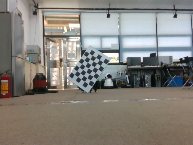
Making calibration plate: the calibration plate should be as large as possible, PDF download of calibration file , there is a set size, and the author adopts A1 - 95mm squares - 7x5 verticies, 8x6 squares . Fix the chessboard paper on a board to align their centers as much as possible and keep the edges parallel. Set parameters in the back. The following figure shows the 7 * 5 internal vertex and 95mm square of A1 size.
-
Setting parameters: mainly modify cam_lidar_calibration/cfg/camera_info.yaml and params yaml
-
camera_info.yaml: set whether it is a fisheye camera, pixel width and height, internal parameter matrix and distortion coefficient. Camera parameters are self calibrated, ROS official calibration tutorial
distortion_model: "non-fisheye"
 width: 640
height: 480
D: [0,0,0,0]
K: [617.68,0.0,325.963,0.0,617.875,242.513,0.0,0.0,1]
-
params.yaml
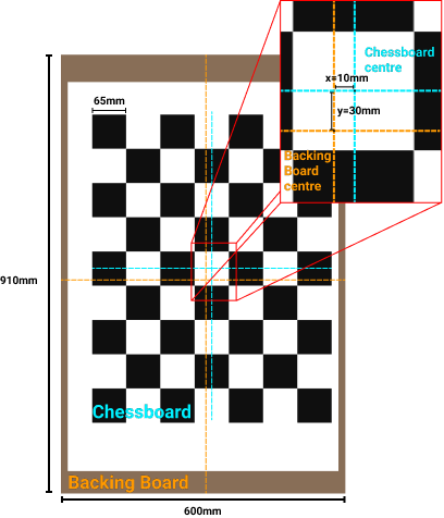
# Topics
camera_topic: "/camera/color/image_raw"
camera_info: "/camera/color/camera_info"
lidar_topic: "/velodyne_points"

#Dynamic rqt_ Default cloud range
feature_extraction:
x_min: -10.0
x_max: 10.0
y_min: -8.0
y_max: 8.0
z_min: -5.0
z_max: 5.0

# Properties of chessboard calibration target
chessboard:
pattern_size:  #Internal vertex of chessboard 7 * 5
height: 7
width: 5
square_length: 95 #Length of chessboard, mm
board_dimension:  # The width and height of the backplane on which the checkerboard print is installed.
width: 594
height: 897
translation_error: #The offset between the chessboard center and the backplane Center (see the figure below).
x: 0
y: 0
Offset between chessboard center and backplane Center
-
-
Officially start calibration:
-
Start the program to collect scheduled data and run the command:
roslaunch cam_lidar_calibration run_optimiser.launch import_samples:=false
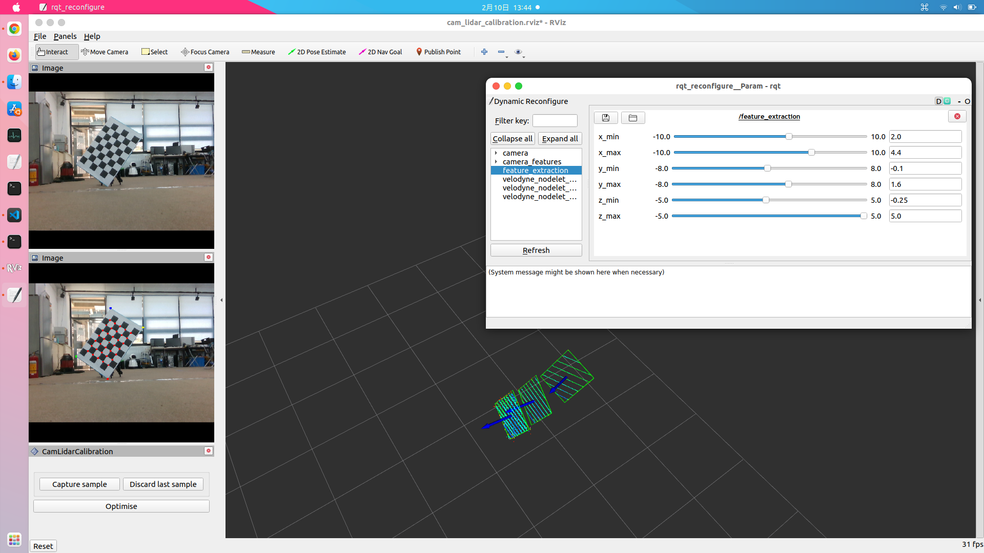
RVIZ and rqt will appear_ In the reconfigure window, in RVIZ, panels - > display, modify the topic of the camera and the frame corresponding to the LIDAR point cloud_ id.
-
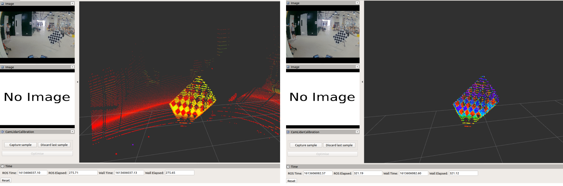
Collect data: segment the point cloud of the calibration board
Adjust rqt_ reconfigure /feature_ The xyz maximum value and minimum value of extraction are used to separate the point cloud of the calibration board from the surrounding environment so that it only displays the chessboard. If the chessboard is not completely isolated, it may affect the plane fitting of the chessboard and lead to large size error of the chessboard. The following figure shows the effect before and after filtering the point cloud:
After filtering the surrounding point cloud, click Capture sample to collect samples in rviz, and the green box will represent the calibration plate plane fitted according to the point cloud, as shown in the figure:
If there is no green fitting rectangle, you need to readjust the XYZ range of the point cloud before collecting samples with capture sample. The laser point cloud needs at least 7 rings to hit the calibration plate. -
Calibration:
At least 3 samples can be collected before calibration. The more samples, the better. It is best to collect more than 10 samples, and then click optimize in rviz for calibration. In the optimization process, it will be in cam_lidar_calibration/data generates the folder of the current time and date, stores the collected images, point cloud pcd, pose, and external reference files of camer a and lidar after calibration. -
Evaluation parameters and re projection errors:
roslaunch cam_lidar_calibration assess_results.launch csv:="$(rospack find cam_lidar_calibration)/data/2022-02-10_13-48-12/calibration_2022-02-10_14-13-41.csv" visualise:=true
Image with re projection effect:
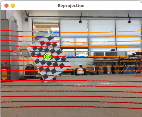
Calibration parameters and re projection errors at the terminal:---- Calculating average reprojection error on 12 samples ---- 1/ 12 | dist= 4.069m, dimerr= 39.768mm | error: 2.948pix --> 20.033mm 2/ 12 | dist= 3.759m, dimerr= 43.992mm | error: 2.358pix --> 14.689mm 3/ 12 | dist= 3.038m, dimerr= 61.650mm | error: 0.240pix --> 1.213mm 4/ 12 | dist= 2.951m, dimerr= 52.597mm | error: 0.129pix --> 0.628mm 5/ 12 | dist= 2.913m, dimerr= 120.838mm | error: 0.782pix --> 3.798mm 6/ 12 | dist= 2.665m, dimerr= 76.147mm | error: 3.219pix --> 14.106mm 7/ 12 | dist= 2.482m, dimerr= 69.678mm | error: 2.728pix --> 11.332mm 8/ 12 | dist= 2.307m, dimerr= 36.923mm | error: 2.659pix --> 10.284mm 9/ 12 | dist= 2.118m, dimerr= 110.454mm | error: 6.066pix --> 21.332mm 10/ 12 | dist= 2.504m, dimerr= 66.145mm | error: 1.402pix --> 5.853mm 11/ 12 | dist= 2.845m, dimerr= 11.296mm | error: 1.408pix --> 6.616mm 12/ 12 | dist= 2.828m, dimerr= 98.653mm | error: 0.719pix --> 3.536mm Calibration params (roll,pitch,yaw,x,y,z): -1.5416,-0.0047,-1.4423,0.0059,-0.0062,0.0149 Mean reprojection error across 12 samples - Error (pix) = 2.055 pix, stdev = 1.663 - Error (mm) = 9.452 mm , stdev = 7.007
-
-