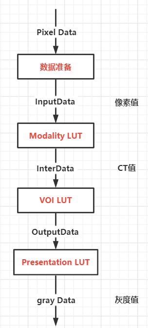
to display medical images in DICOM format, the original image data must undergo a series of transformations to obtain data that can be directly displayed on the display device (called P Values). DICOM medical image display needs three conversion processes: Modality LUT, VOI LUT and Presentation LUT, and the final output P Values is the image data that can be displayed directly.
LUT is the abbreviation of Look Up Table, VOI is the abbreviation of Volume of Interest, and P Values is the abbreviation of Presentation Values.

1, Protocol analysis
1.1 Modality LUT
generally, it is difficult for the equipment of different manufacturers to ensure that the images generated on one equipment are consistent with the images generated on the same type of equipment of other manufacturers. Therefore, it is necessary to convert the original data of the images generated by different equipment manufacturers to a standard measurement space. The modification LUT conversion completes this function.
taking CT imaging technology as an example, we already know that the gray range of human body is - 1000 to + 1000, but there may be deviation in the collected data due to different equipment manufacturers. For example, suppose that the standard range of organization A is 50 to 200, but the standard range of equipment manufacturer 1 may be 60 to 210, and that of equipment 2 may be 40 to 190. If each manufacturer's equipment has deviation, we can't judge the tissue according to the gray value (because when my lung is detected at 150, it may become 140 when I arrive at you). Therefore, DICOM standard requires equipment manufacturers to convert the gray range of their own equipment to the standard range of - 1000 ~ 1000 when exporting data. In other words, the Modality LUT is A transformation mapping between the equipment manufacturer itself and the standard.
the elements related to Modality LUT are shown in the following figure

Modality LUT provides linear and nonlinear mapping methods, look-up table nonlinear conversion and slope / intercept linear conversion.
The Modality LUT lookup table method is a nonlinear transformation algorithm. A lookup table consists of many data items. Each data item is the data value converted from the corresponding original value. At the same time, it also provides a data value converted to the original data of the first data item of the lookup table.
Rescale / intercept transformation is a linear transformation. The formula used is: standard image pixel value = original image pixel value * slope + intercept. The slope and intercept can be read in DICOM file.
Hu = pixel * slope + intercept
after this step, the image pixels will change from device related to device independent.
1.2 volume LUT conversion
most of the output values of medical images are 12 or 16bit, while the gray level that human eyes can actually distinguish is about 8bit, and most displays can only display 256 gray levels. Even for professional medical image display, its gray resolution only reaches the level of 10 to 12 bit, which is still a big gap from 16 bit. In order to display these high color and deep medical images on the screen, it is inevitable to compress the image data range to 8bit, which is a typical lossy conversion, and this conversion is easy to highlight the noise part in the image.
the elements related to volume LUT are shown in the following figure
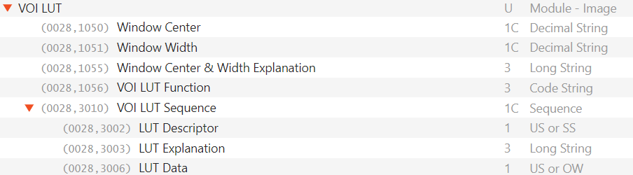
in order to highlight the details of the region of interest, volume LUT transformation also provides linear and nonlinear mapping methods, look-up table nonlinear transformation and window width and window level linear transformation.
linear mapping, that is, the window width and window level adjustment algorithm concerned by clinicians. The transformation defines some better mapping algorithms, makes full use of the display effective value range between 0 ~ 255, reduces the loss caused by value range compression, and highlights the tissue part of interest to doctors as much as possible, which meets the special requirements of gray processing of medical images. See formula (1) for the standard formula, where all input values are integers, and the window width w must be greater than 1. Where: w is the window width; c is window level; xmin is the minimum input value; xmax is the maximum input value; fmin is the minimum output value; fmax is the maximum output value.
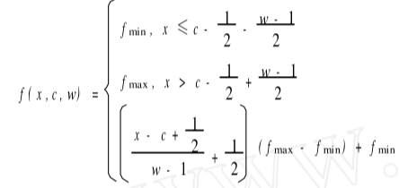
min = (2 * wl - ww) / 2.0 + 0.5;
max = (2 * wl + ww) / 2.0 + 0.5;
gray_value = (ct_value - min) * 255.0 / (max - min)
window width and window level linear conversion algorithm is to obtain the window size (window width) and center position (window level) to be displayed according to the predicted window width and window level values, so as to linearly convert the image data of the window area to the maximum range of the display, and the image data higher or lower than the upper and lower limits of the window are set as the highest or darkest display values respectively.
here, the window width refers to the range of the image to be displayed. Adjusting the window width mainly affects the contrast. The larger the window width, the more gray levels of the image, the reduced tissue contrast and the poor detail display. The window level is also called the window center, which indicates the center position of the display area. For example, the window level and window width of the bone are 3001500 respectively. Then the window width can be adjusted to the bone window width by using the window adjustment process, Adjust the window level to the window level of the bone, and then use the above formula to convert the image V into the display value of the display. The final result is that only the image within the window range, that is, the bone, is displayed.
one or more pairs of windows provided by DICOM pictures themselves are stored in window center (00281050) and window width (00281051) elements. For pictures without windows, generally take xmax - xmin as the window width and (xmax + xmin)/2 as the window level for linear mapping.
sometimes, linear mapping has little effect on images with too wide window or too small lesion and too small density difference from surrounding normal tissue. In this case, the technician will use some nonlinear conversion on the acquisition workstation to improve the contrast and compensate the nonlinear response of human eyes to light. This kind of nonlinear transformation can not be deduced simply by window width and window level. Therefore, DICOM standard stores this kind of nonlinear mapping relationship in the voilut sequence (00283010) sequence in the form of look-up table. The sequence includes three DICOM elements: LUT descriptor (00283002), LUT explanation (00283003) and LUT data (00283006).
generally speaking, if there is a Voilut Sequence element in the DICOM file, you must first use the Voilut look-up table method for mapping. Like linear mapping, an image can provide one or more lookup tables. Different look-up tables map the image information of different gray areas. In practical use, the frequently used nonlinear mappings include logarithmic mapping, SigMoid mapping and so on.
1.3 Presentation LUT
the last transformation to be made to the image pixel, which is used for the display of a specific image. The first mock exam is P Values, and P Values is a value independent of any display device's characteristic curve and similar to human visual reaction. It can be used as a corrected soft copy device or hard copy input directly. Presentation LUT refers to the nonlinear characteristics of human visual characteristic curve, and transforms the input data so that the gray output value Presentation Values(P-Values) is directly proportional to the gray visual characteristics of human eyes. P-Values is independent of the characteristic curve of the specified display device and is an input of the standard display device. Presentation LUT is commonly used in orthopedic image display. The contrast is improved by nonlinear correction curve in order to find the broken seam in the patient's bone.
elements related to Presentation LUT are shown in the following figure
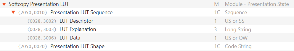
Presentation LUT transformation also provides linear and nonlinear mapping methods. Look up table nonlinear transformation and Presentation Shape linear transformation can only use one of these two transformation methods.
the process of Presentation LUT conversion is basically the same as the two LUT algorithms introduced above.
Presentation Shape uses either index or invert. Index refers to the data value converted by VOI LUT, i.e. P-Values value, which does not need to be converted. This value is used for soft copy of general image; The value of invert shall have the same meaning as the value of IDENTITY, but the minimum output value shall represent the meaning of the maximum available brightness, and the maximum value shall represent the minimum available brightness.
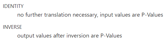
Invert is calculated as follows:
P-Value = maximum value - output value
common DICOM images generally only need two conversion processes: Modality LUT and VOI LUT. Generally, Presentation LUT conversion is not used.
2, Source code analysis
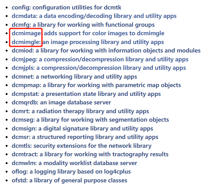
the DicomImage class of dcmimgle module is used in dcmtk. If it is a monochrome image, only dcmimgle module is required, and if it is a color image, dcmimage module is also required.
the corresponding relationship between the converted data of Modality LUT, VOI LUT and Presentation LUT and the module / method of dcmtk is as follows:
the return value of getUint8Array method of dcmdata module is the original Pixel Data
the return value of getUint16Array method of dcmdata module is the data related to the device
the return value of getInterData method of dcmimgle module is the data converted by Modality LUT
the return value of getOutputData method of dcmimgle module is the converted data of volume LUT and Presentation LUT.
after instantiation, the DicomImage class of dcmimgle module can obtain the data after modification LUT conversion and volume LUT conversion. The dcmtk source code is analyzed below.
dicomImg = new DicomImage(dcmParse->GetDataSet(), EXS_LittleEndianExplicit);
const DiPixel *diPixel = dicomImg->getInterData();
EP_Representation rep = diPixel->getRepresentation();
switch (rep) {
case EPR_Sint8:
	break;
case EPR_Uint8:
	break;
case EPR_Sint16:
	//Modality LUT converted data
	CTValue = (signed short*)diPixel->getData();
	break;
//Volume LUT and Presentation LUT converted data
unsigned char *pixelDataGrey = (unsigned char*)(dicomImg->getOutputData(8, 0, 0));
2.1 obtaining pixel data of equipment correlation diagram
convert (7fe00010) pixel data into Modality LUT input data InputData
convert pixel data from DICOM dataset to input representation
DicomImage calls DiMono2Image internally
Image = new DiMono2Image(Document, ImageStatus)
DiMono2Image inherits DiMonoImage, DiMonoImage inherits DiImage, DiImage constructor calls convertPixelData() method, convertPixelData method converts Pixel Data data stored in Dicom to data related to device related 8bit, that is, input of input.
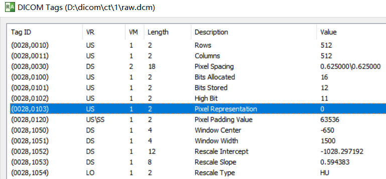
here, call the corresponding method according to BitsStored=12 and Pixel Representation=0.
else if (BitsStored <= 16)
{
	//Judge whether the data stored in (7fe00010) pixel data is signed or unsigned according to (00280103) pixel representation
     if (hasSignedRepresentation)
         InputData = new DiInputPixelTemplate<Uint16, Sint16>(Document, BitsAllocated, BitsStored, HighBit, FirstFrame, NumberOfFrames, fsize, &FileCache, CurrentFragment);
     else
         InputData = new DiInputPixelTemplate<Uint16, Uint16>(Document, BitsAllocated, BitsStored, HighBit, FirstFrame, NumberOfFrames, fsize, &FileCache, CurrentFragment);
 }
because the cpu architecture determines the size end format of the operating system, for example, x86 is a little endian, while PPC (PowerPC) is a big endian. Therefore, linux/windows running on X86 is a small end format. Generally, personal computers and service areas are x86 architecture.
if the 16bit data itself is stored in small end format, the operating system itself can correctly identify it. If the 16bit data itself is stored in the big end format, the first and second bytes need to be shifted as a whole and converted into the small end format before the operating system can correctly recognize it.
for example, win10 system under intel i5 cpu:
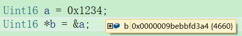
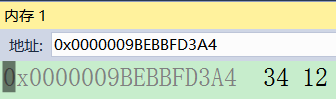
0x1234 the high byte is 0x12 and the low byte is 0x34. The order of bytes stored in the memory pointed to by the pointer address is that the low byte 0x34 comes first and the high byte 0x12 comes later, that is, small end format storage. The decimal value of 0x1234 is 4660, which vs can be recognized correctly.
therefore, the DICOM image data in small end format does not need to be converted, and the system can recognize it correctly. The big end format needs to be converted.
the internal core code of diinpixeltemplate function obtains 16bit data from 8bit Pixel Data
static Uint32 getPixelData(DcmPixelData *PixelData,
                           Uint16 *&pixel)
{
    PixelData->getUint16Array(pixel);
    return PixelData->getLength();
}
The getUint16Array function internally calls DcmElement::getValue
void *DcmElement::getValue(const E_ByteOrder newByteOrder)
The core code of getValue function. If it is a big end, execute swapIfNecessary
/* if this element's value's byte ordering does not correspond to the */
/* desired byte ordering, we need to rearrange this value's bytes and */
/* set its byte order indicator variable correspondingly */
if (newByteOrder != fByteOrder)
{
swapIfNecessary(newByteOrder, fByteOrder, fValue,
                getLengthField(), getTag().getVR().getValueWidth());
swapIfNecessary function internal core code, high and low byte shift
Uint8 *first = &OFstatic_cast(Uint8*, value)[0];
Uint8 *second = &OFstatic_cast(Uint8*, value)[1];
Uint32 times = byteLength / 2;
while(times)
{
    --times;
    save = *first;
    *first = *second;
    *second = save;
    first += 2;
    second += 2;
}
2.2. Modality LUT conversion
the input is the equipment related InputData, and the output is the CT value InterData.
in the DiMonoImage constructor, instantiate the DiMonoModality object, read the corresponding element from the DICOM file, and fill in the modality object
DiMonoModality *modality = new DiMonoModality(Document, InputData);
calculate the minimum and maximum values of the output InputData in the previous step to obtain the maximum and minimum values after the conversion of the Modality LUT, and judge whether it is signed or not.
the example here is 16 bit signed data.
MinValue = pixel->getMinValue(1 /* selected range of pixels only */);
MaxValue = pixel->getMaxValue(1 /* selected range of pixels only */);
MinValue = MinValue * RescaleSlope + RescaleIntercept;
MaxValue = MaxValue * RescaleSlope + RescaleIntercept;
void DiMonoModality::determineRepresentation(const DiDocument *docu)
{
    UsedBits = DicomImageClass::rangeToBits(MinValue, MaxValue);
    if ((docu != NULL) && (docu->getFlags() & CIF_UseAbsolutePixelRange))
        Representation = DicomImageClass::determineRepresentation(AbsMinimum, AbsMaximum);
    else
        Representation = DicomImageClass::determineRepresentation(MinValue, MaxValue);
    DCMIMGLE_TRACE("internal representation for monochrome images: "
        << DicomImageClass::getRepresentationBits(Representation) << " bits ("
        << (DicomImageClass::isRepresentationSigned(Representation) ? "signed" : "unsigned") << ")");
}

the output InputData in the previous step is used as the Modality LUT input for conversion,
Inputdata - > getrepresentation () is the value represented by (00280103) pixel representation. Here is 0, which means that (7fe00010) pixel data stores an unsigned value. Execute EPR_Uint16 branch.
switch (InputData->getRepresentation())
{
    case EPR_Uint8:
        InitUint8(modality);
        break;
    case EPR_Sint8:
        InitSint8(modality);
        break;
    case EPR_Uint16:
        InitUint16(modality);
        break;
void DiMonoImage::InitUint16(DiMonoModality *modality)
{
    if (modality != NULL)
    {
        switch (modality->getRepresentation())
        {
            case EPR_Uint8:
                InterData = new DiMonoInputPixelTemplate<Uint16, Uint32, Uint8>(InputData, modality);
                break;
            case EPR_Sint8:
                InterData = new DiMonoInputPixelTemplate<Uint16, Uint32, Sint8>(InputData, modality);
                break;
            case EPR_Uint16:
                InterData = new DiMonoInputPixelTemplate<Uint16, Uint32, Uint16>(InputData, modality);
                break;
            case EPR_Sint16:
                InterData = new DiMonoInputPixelTemplate<Uint16, Uint32, Sint16>(InputData, modality);
                break;
DiMonoInputPixelTemplate internal call
rescale(pixel, this->Modality->getRescaleSlope(), this->Modality->getRescaleIntercept());
rescale internal call
for (i = 0; i < ocnt; ++i)
	*(q++) = OFstatic_cast(T3, (OFstatic_cast(double, i) + absmin) * slope + intercept);
At this point, the DicomImage constructor completes:
1. Convert (7fe00010) pixel data into Modality LUT input data InputData
2. Convert the InputData related to the equipment into Modality LUT to obtain the CT value interdiata
For CT images, the return value of dicomimg - > getinterdata() is the CT value.
2.3 volume LUT and presentation LUT conversion
the input is the CT value interdiata, and the output is the gray value OutputData
unsigned char *pixelDataGrey = (unsigned char*)(dicomImg->getOutputData(8, 0, 0));
internal call, EPR according to the data type stored in InterData_ Sint16 branch
switch (InterData->getRepresentation())
{
     case EPR_Uint8:
         getDataUint8(buffer, disp, samples, frame, bits, low, high);
         break;
     case EPR_Sint8:
         getDataSint8(buffer, disp, samples, frame, bits, low, high);
         break;
     case EPR_Uint16:
         getDataUint16(buffer, disp, samples, frame, bits, low, high);
         break;
     case EPR_Sint16:
         getDataSint16(buffer, disp, samples, frame, bits, low, high);
         break;
convert Sint16 to Uint8
void DiMonoImage::getDataSint16(void *buffer,
                                DiDisplayFunction *disp,
                                const int samples,
                                const unsigned long frame,
                                const int bits,
                                const Uint32 low,
                                const Uint32 high)
{
    if (bits <= 8)
        OutputData = new DiMonoOutputPixelTemplate<Sint16, Sint32, Uint8>(buffer, InterData, Overlays, VoiLutData, PresLutData,
            disp, VoiLutFunction, WindowCenter, WindowWidth, low, high, Columns, Rows, frame, NumberOfFrames, samples > 1);
    else if (bits <= 16)
        OutputData = new DiMonoOutputPixelTemplate<Sint16, Sint32, Uint16>(buffer, InterData, Overlays, VoiLutData, PresLutData,
            disp, VoiLutFunction, WindowCenter, WindowWidth, low, high, Columns, Rows, frame, NumberOfFrames);
    else
        OutputData = new DiMonoOutputPixelTemplate<Sint16, Sint32, Uint32>(buffer, InterData, Overlays, VoiLutData, PresLutData,
            disp, VoiLutFunction, WindowCenter, WindowWidth, low, high, Columns, Rows, frame, NumberOfFrames);
}
DiMonoOutputPixelTemplate internal call
first judge whether there is a voilut nonlinear lookup table. If not, use the window width and window level for linear conversion.
if ((vlut != NULL) && (vlut->isValid()))            // valid VOI LUT ?
   voilut(pixel, frame * FrameSize, vlut, plut, disp, OFstatic_cast(T3, low), OFstatic_cast(T3, high));
else
{
   if (width < 1)                                  // no valid window according to supplement 33
       nowindow(pixel, frame * FrameSize, plut, disp, OFstatic_cast(T3, low), OFstatic_cast(T3, high));
   else if (vfunc == EFV_Sigmoid)
       sigmoid(pixel, frame * FrameSize, plut, disp, center, width, OFstatic_cast(T3, low), OFstatic_cast(T3, high));
   else // linear
       window(pixel, frame * FrameSize, plut, disp, center, width, OFstatic_cast(T3, low), OFstatic_cast(T3, high));
}
widnow function judges the presentation LUT first. If the presentation LUT is used, the presentation LUT and linear voilut are executed together. If there is no linear voilut, the linear voilut conversion is executed
if ((plut != NULL) && (plut->isValid()))                              // has presentation LUT
{
    DCMIMGLE_DEBUG("applying presentation LUT transformation");
    createDisplayLUT(dlut, disp, plut->getBits());
    Uint32 value2;                                                    // presentation LUT is always unsigned
    const Uint32 pcnt = plut->getCount();
    const double plutmax_1 = OFstatic_cast(double, plut->getAbsMaxRange()) - 1;
    const double gradient1 = (width_1 == 0) ? 0 : OFstatic_cast(double, pcnt - 1) / width_1;
    if (initOptimizationLUT(lut, ocnt))
    {                                                                 // use LUT for optimization
        q = lut;
        if (dlut != NULL)                                             // perform display transformation
        {
            DCMIMGLE_TRACE("monochrome rendering: VOI LINEAR #1");
            const double maxvalue = OFstatic_cast(double, dlut->getCount() - 1);
the core code of linear voilut conversion is
const double offset = (width_1 == 0) ? 0 : (high - ((center - 0.5) / width_1 + 0.5) * outrange);
const double gradient = (width_1 == 0) ? 0 : outrange / width_1;
for (i = 0; i < ocnt; ++i)                                 // calculating LUT entries
{
    value = OFstatic_cast(double, i) + absmin;
    if (value <= leftBorder)
        *(q++) = low;                                            // black/white
    else if (value > rightBorder)
        *(q++) = high;                                           // white/black
    else
        *(q++) = OFstatic_cast(T3, offset + value * gradient);   // gray value
}
3, Summary
data processing flow of Modality LUT, VOI LUT, Presentation LUT and dcmtk
 InputData = new DiInputPixelTemplate<Uint16, Uint16>(Document, BitsAllocated, BitsStored, HighBit, FirstFrame, NumberOfFrames, fsize, &FileCache, CurrentFragment);
 InterData = new DiMonoInputPixelTemplate<Uint16, Uint32, Sint16>(InputData, modality);
 OutputData = new DiMonoOutputPixelTemplate<Sint16, Sint32, Uint8>(buffer, InterData, Overlays, VoiLutData, PresLutData,
            disp, VoiLutFunction, WindowCenter, WindowWidth, low, high, Columns, Rows, frame, NumberOfFrames, samples > 1);
dcmdata module can only obtain element values without image pixel processing. It can only obtain meaningful pixel values according to (7fe00010) pixel data, (00280100) Bits Allocated and (00280103) Pixel Representation. If the Pixel Representation is 0 and Bits Allocated is 16, it is obtained by using the getUint16Array method of dcmdata module. For CT images, the return value of getUint16Array is device related data.
dcmimgle module's dcmimge class encapsulates the process of image pixel processing, which can process 8bit, 16bit, sign, unsign ed and other data, and obtain pixel data in multiple stages.