preface
in the previous course, we learned led light control, key anti chattering, key control buzzer and so on. This paper will introduce the state machine. Based on the previous courses, the state machine will be used to design the water lamp and simulate the electronic door lock.
1, Introduction to finite state machine
finite state machine (FSM), also known as finite state automata, or state machine for short, refers to a sequential circuit that converts between finite states according to a certain law.
2, Application of finite state machine
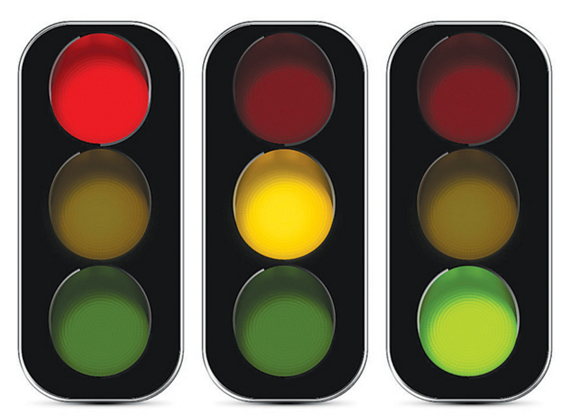
2.1 traffic lights
the traffic light of the motorway is actually a running light realized by the finite state machine, but the flashing interval of the traffic light is different. Generally, the yellow light is 3s, the red light is 60s and the green light is 20s. We set the flashing interval in the running water lamp to be equal. In the fourth section of this paper, we will use finite state machine to implement water lamp.
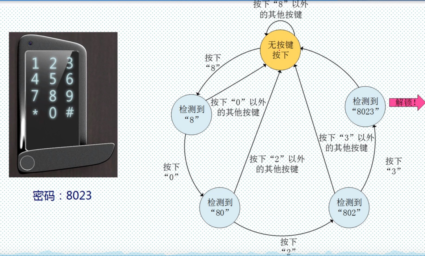
2.2 electronic door lock
the process of password unlocking is also a finite state machine. The electronic lock can be opened only by entering the password in the correct order.
3, Finite state machine model
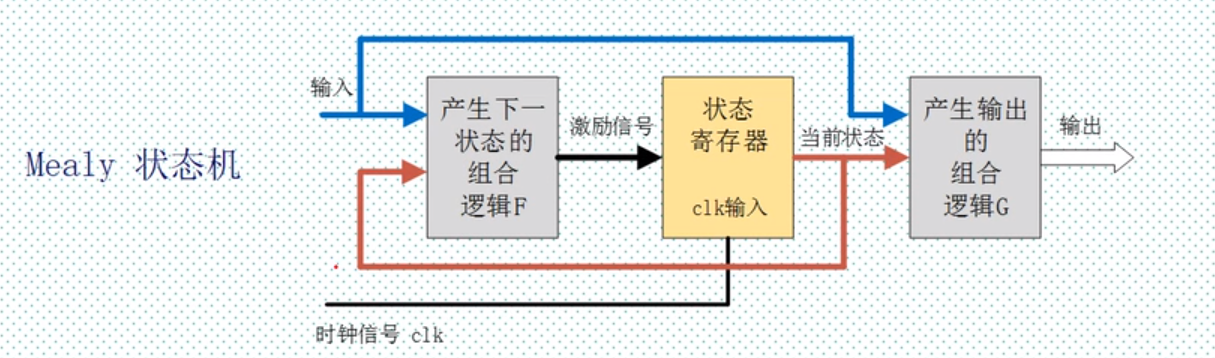
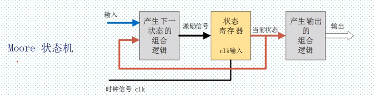
finite state machines mainly include Miley state machine and Moore state machine. The state machine whose output is directly related to the input variable is called Millie state machine, and the state machine whose output is not directly related to the input variable is called Moore state machine.
3.1 Millie state machine
3.2 Moore state machine
4, FSM realizes flow lamp
4.1 fsm_led source code
module 	fsm_led(
	input 					clk  ,//Clock signal, 50MHz
	input 					rst_n,//Reset signal, falling edge valid

	output 	reg [3:0]	led//4 led lights
);

parameter 	TIME = 50_000_000;//Interval 1s
//state space
parameter 	S_LED0 = 2'd0;
parameter 	S_LED1 = 2'd1;
parameter 	S_LED2 = 2'd2;
parameter 	S_LED3 = 2'd3;
//Status of four led lights
parameter 	LED0 = 4'b0001;
parameter 	LED1 = 4'b0010;
parameter 	LED2 = 4'b0100;
parameter 	LED3 = 4'b1000;
reg [25:0]	cnt;//Clock counter
reg [1:0]	current_stat;//Current status register

//Timing module
always@(posedge clk or negedge rst_n)begin
	if(!rst_n)begin//reset
		cnt <= 26'd0;//Counter clear 0
	end
	else if(cnt == TIME - 1)begin//Full 1s
		cnt <= 26'd0;//Counter clear 0
	end
	else begin
		cnt <= cnt + 26'd1;//Other times plus 1
	end
end

//State switching
always@(posedge clk or negedge rst_n)begin
	if(!rst_n)begin
		current_stat <= 2'd0;//The current state is initialized to 0
	end
	else begin
		case(current_stat)
		S_LED0:	begin//When the status is 0
						if(cnt == TIME - 1)begin//Full 1s
							led <= LED1;//led light switch 0010 status
							current_stat <= S_LED1;//Status register switch 2'd1
						end
						else begin
							led <= LED0;//Otherwise, keep 0001
							current_stat <= S_LED0;//Keep the original state
						end
					end
		S_LED1:	begin
						if(cnt == TIME - 1)begin//Full 1s
							led <= LED2;//led switch 0100 status
							current_stat <= S_LED2;//Status register switch 2'd2
						end
						else begin
							led <= LED1;//Otherwise, maintain 0100 status
							current_stat <= S_LED1;//Status register switch 2'd1
						end
					end
		S_LED2:	begin
						if(cnt == TIME - 1)begin//Full 1s
							led <= LED3;//led switch 1000 status
							current_stat <= S_LED3;//Status register switch 2'd3
						end
						else begin
							led <= LED2;//led switch 0100 status
							current_stat <= S_LED2;//Status register switch 2'd2
						end
					end
		S_LED3:	begin
						if(cnt == TIME - 1)begin//Full 1s
							led <= LED0;//led light switch 0001 status
							current_stat <= S_LED0;//Status register switch 2'd0
						end
						else begin
							led <= LED3;//led switch 1000 status
							current_stat <= S_LED3;//Status register switch 2'd3
						end
					end
		default:;
		endcase
	end
end


endmodule
4.2 fsm_led_tb test file code
`timescale 1ns/1ns//Unit / accuracy
module	fsm_led_tb();

parameter 	CYCLE = 5'd20;//The cycle is 20ns
parameter 	TIME  = 4'd10;//The interval of running water lamp is 10*20=200ns
reg 		clk		     ;//Clock
reg 		rst_n	     ;//Reset signal, falling edge valid
wire [3:0]	led			 ;//Four led lights

always #(CYCLE/2) clk = ~clk;// Flip every 10ns

initial begin//Initialization signal
	clk 	= 1'b0     ;//The clock signal is initialized to 0
	rst_n   = 1'b0     ;//The reset signal is initialized to 0
	#(CYCLE/2)         ;// Wait 10ns
	rst_n   = 1'b1     ;//Reset signal pull high level
	#(CYCLE * TIME * 4);// Wait for 20*10*4ns to observe the signals of the four led lights of the water lamp
	$stop              ;//stop it

end

//Instantiation test module
fsm_led	#(.TIME (TIME)) u_fsm_led(/ / take another name
.clk		(clk)  ,//Clock signal, 50MHz
.rst_n	    (rst_n),//Reset signal, falling edge valid

.led		(led)//4 led lights
);
endmodule
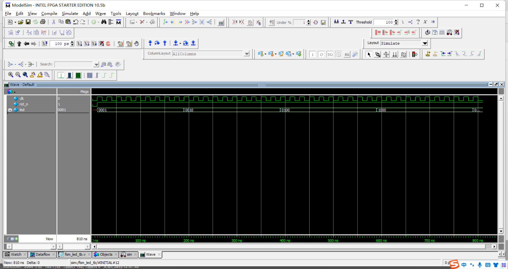
4.3 function simulation
6, Pin assignment
| element | Pin |
|---|---|
| LED0 | G15 |
| LED1 | F16 |
| LED2 | F15 |
| LED3 | D16 |
| KEY0 | E15 |
| KEY1 | E16 |
| KEY2 | M16 |
| KEY3 | M15 |
| Colock (clock) | E1 |
summary
the above is what we want to talk about today. This paper only briefly introduces the finite state machine, the main models of the finite state machine, and the implementation of the finite state machine. Finite state machine is widely used, including the electronic door lock in this paper. Interested students can use the keys and LEDs on the cyclone IV development board to simulate the unlocking process of the electronic door. Because the final function is similar to the running water lamp, the video demonstration effect will not be uploaded in this paper. Thank you for watching!