preface
in the last course, we learned about nixie tube and realized the static display of nixie tube through code. This course will continue the content of the previous lesson and explain the dynamic display of nixie tube.
tip: I learned about nixie tube last class, so I skipped the explanation of nixie tube and began to explain directly from the nixie tube driver.
1, Nixie tube drive
since segment selection signals are shared, as shown in Figure 2, only one nixie tube can be selected at the same time. The specific selection of ten bits or one bit is determined by the bit selection signal.
Q: in this way, only one nixie tube can be selected at a time. How can multiple nixie tubes be selected at the same time?
answer: visual persistence: when an object moves rapidly, the residual influence in the brain will remain for a period of time.
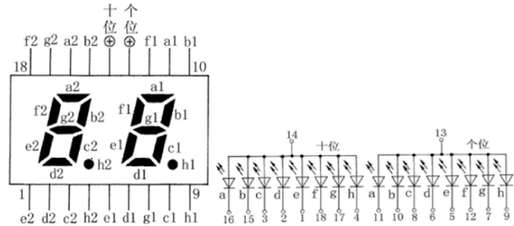
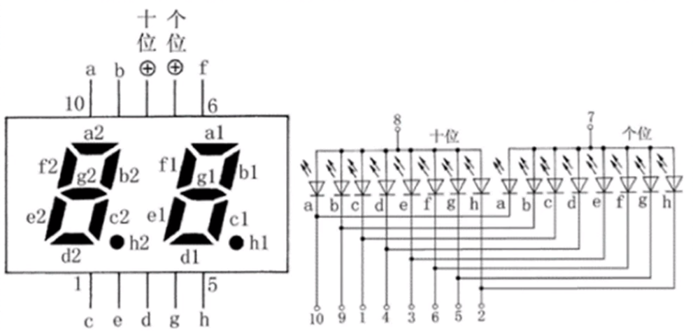 Figure 2 Nixie tube dynamic display
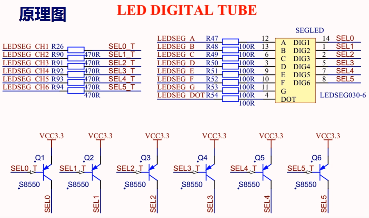
2, Schematic diagram of nixie tube
in the schematic diagram, in addition to the segment selected signal of the nixie tube, there are also the unselected signal of the nixie tube. The nixie tube bit selection and segment selection signals are effective at low level.
3, Experimental task
3.1 task description
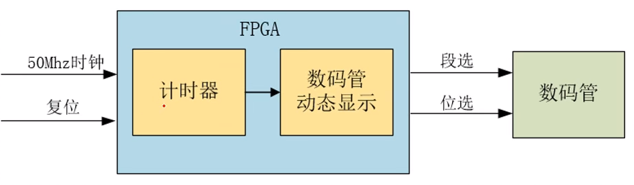
by using 6-bit nixie tube dynamic display, a timer changes every 0.5 seconds and displays the number 123456. The module design is shown in Figure 4. A top-level module calls two sub modules, time_count is the timing module, sel_led_dynamic is a nixie tube dynamic display module, top_sel_led_dynamic is the top-level module.
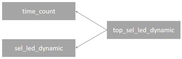
3.2 system block diagram
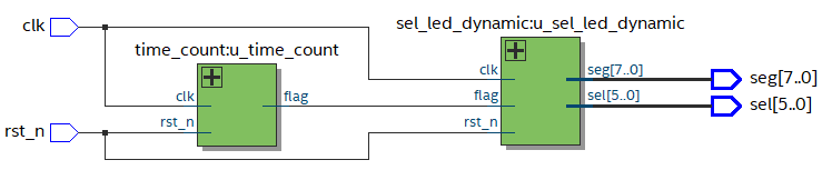
3.3 module schematic diagram
3.4 module code
- Create time_count file and write time_count module code.
module time_count(
	input 	clk,//Clock frequency, 50MHz
	input	 	rst_n,//Reset signal, falling edge valid

	output reg	flag//Pulse signal of one clock cycle

);

parameter 	MAX_NUM = 25'd25_000_000;//0.5s clock
reg [24:0]	cnt							;//Clock counter

//The timer counts the clock and outputs a clock cycle pulse signal every 0.5s
always@(posedge clk or negedge rst_n)begin
	if(!rst_n)begin//When the reset signal is pressed
		cnt <= 25'd0;//Counter setting bit 0
		flag <= 1'b0;//Periodic pulse signal setting bit 0
	end
	else if(cnt == MAX_NUM - 1'd1)begin//If the time comes
		cnt <= 25'd0;//Counter reset
		flag <= 1'b1;//The output of periodic pulse signal is 1, which means that the recording is slow by one cycle
	end
	else begin//If the time is not up
		cnt <= cnt + 1'd1;//The counter keeps counting
		flag <= 1'b0;//The periodic pulse signal remains unchanged
	end
end


endmodule
- Create sel_led_dynamic file and write sel_led_dynamic module code.
module sel_led_dynamic(
	input 				clk  ,//Clock, 50MHz
	input 				rst_n,//Reset signal, falling edge valid
	input 				flag ,//Periodic signal

	output reg [5:0]	sel  ,//Bit selection signal, six nixie tubes
	output reg [7:0]	seg  //Segment selection signal, eight Segment led

);

reg [2:0]	cstat ;//current state
reg [2:0]	nstat ;//Next status

//state transition
always@(posedge clk or negedge rst_n)begin
	if(!rst_n)begin//Falling edge effective
		cstat <= 3'd0;//The current status is set to 0
	end
	else begin
		cstat <= nstat;//state transition
	end
end

//Next state judgment (combinational logic)
always@(*)begin

	case(cstat)
		3'd0:	if(flag)begin
					nstat = 3'd1;
				end
				else begin
					nstat = 3'd0;
				end
		3'd1: if(flag)begin
					nstat = 3'd2;
				end
				else begin
					nstat = 3'd1;
				end
		3'd2: if(flag)begin
					nstat = 3'd3;
				end
				else begin
					nstat = 3'd2;
				end
		3'd3: if(flag)begin
					nstat = 3'd4;
				end
				else begin
					nstat = 3'd3;
				end
		3'd4: if(flag)begin
					nstat = 3'd5;
				end
				else begin
					nstat = 3'd4;
				end
		3'd5: if(flag)begin
					nstat = 3'd0;
				end
				else begin
					nstat = 3'd5;
				end
	default:	nstat= 3'd1;
	endcase
end

reg [2:0] value;

//Actions in various states (can be combined or sequential)
always@(*)begin
	if(!rst_n)begin
		value = 3'd0;
	end
	else begin
		case(cstat)
			3'd0:   begin
							 sel = 6'b111_110;//Select the rightmost nixie tube. sel low effective
							 value = 3'd1;
					end
			3'd1:   begin
							 sel = 6'b111_101;
							 value = 3'd2;
					end
			3'd2:   begin
							 sel = 6'b111_011;
							 value = 3'd3;
					end
			3'd3:   begin
							 sel = 6'b110_111;
							 value = 3'd4;
					end
			3'd4:   begin
							 sel = 6'b101_111;
							 value = 3'd5;
					end
			3'd5:   begin
							 sel = 6'b011_111;
							 value = 3'd6;
					end
		   default:		begin//The default is case 1
							 sel = 6'b111_110;
							 value = 3'd1;
					  	end
		endcase
	end
end

//Output of digital tube seg
always@(*)begin
	if(!rst_n)begin
		 seg = 8'b00000000;
	end
	else begin
		case(value)
			 3'd1:   seg = 8'b11111001;//According to the nixie tube truth table
			 3'd2:   seg = 8'b10100100;
			 3'd3:   seg = 8'b10110000;
			 3'd4:   seg = 8'b10011001;
			 3'd5:   seg = 8'b10010010;
			 3'd6:   seg = 8'b10000010;
			 default :   seg = 8'b00000000;
		endcase
	end
end

endmodule
- Create top_sel_led_dynamic file and write top_sel_led_dynamic module code.
module top_sel_led_dynamic(
	input 			clk  ,//Clock signal, 50MHz
	input 			rst_n,//Reset signal, falling edge valid

	output [5:0]	sel  ,//Bit selection signal
	output [7:0]	seg   //Segment selection signal
);
wire flag;//wire connects the two modules
parameter	MAX_NUM = 25'd25_000_000;
time_count #(.MAX_NUM(MAX_NUM)) 	 u_time_count(/ / instantiate timer module
.clk		(clk)  ,//Clock frequency, 50MHz
.rst_n		(rst_n),//Reset signal, falling edge valid

.flag		(flag)  //Pulse signal of one clock cycle

);

sel_led_dynamic	u_sel_led_dynamic(//Instantiate nixie tube dynamic display module
.clk  	(clk)  ,//clock signal
.rst_n	(rst_n),//Reset signal, falling edge valid
.flag 	(flag) ,//Periodic signal

.sel  	(sel)  ,//Bit selection signal, six nixie tubes
.seg  	(seg)   //Segment selection signal, eight Segment led

);

endmodule
3.5 test code
create top_sel_led_dynamic_tb test file, and write top_sel_led_dynamic_tb test module code.
`timescale 1ns/1ns//Unit: 1ns / accuracy: 1ns
module top_sel_led_dynamic_tb();

reg 			clk  ;
reg 			rst_n;
wire [5:0]		sel  ;
wire [7:0]		seg  ;

parameter CYCLE = 5'd20   ;//20ns
parameter MAX_NUM = 7'd100;//Timing 100x20ns

always #(CYCLE/2) clk = ~clk;//10ns flip clock

initial begin
	clk = 1'b0			  ;//Clock set to 0
	rst_n = 1'b0		  ;//Reset signal set to 0
	#(CYCLE) 			  ;// Delay 20ns
	rst_n = 1'b1		  ;//Reset signal set to 1
	#(MAX_NUM * CYCLE * 6);// Watch the six nixie tubes
	$stop				  ;//stop it
end
top_sel_led_dynamic	#(.MAX_NUM(MAX_NUM)) u_top_sel_led_dynamic(
.clk  	(clk)  ,//Clock signal, 50MHz
.rst_n	(rst_n),//Reset signal, falling edge valid

.sel  	(sel)  ,//Bit selection signal
.seg   	(seg)//Segment selection signal
);
endmodule
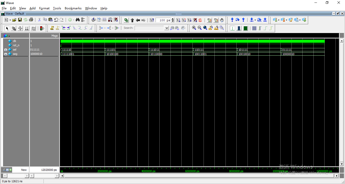
3.6 function simulation
in the functional simulation, the difference from the static display of nixie tube is that the sel bit selection signal keeps changing. seg is a segment selection signal, and different segment selection signals correspond to 1-6 digits.
4, Pin assignment
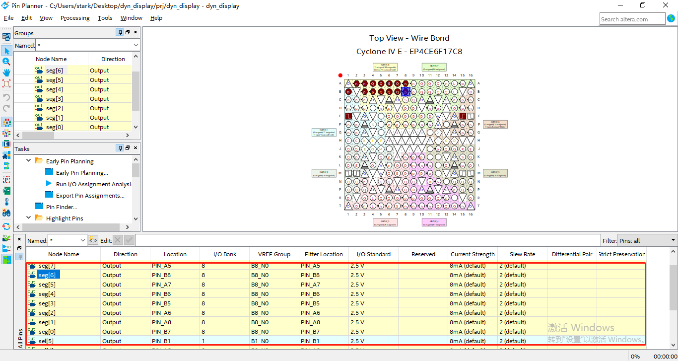
| element | Pin |
|---|---|
| SEL0 | A4 |
| SEL1 | B4 |
| SEL2 | A3 |
| SEL3 | B3 |
| SEL4 | A2 |
| SEL5 | B1 |
| DIG0 | B7 |
| DIG1 | A8 |
| DIG2 | A6 |
| DIG3 | B5 |
| DIG4 | B6 |
| DIG5 | A7 |
| DIG6 | B8 |
| DIG7 | A5 |
| CLOCK (CLOCK) | E1 |
| KEY1 | E15 |
5, Operation effect
Nixie tube dynamic display
summary
in this course, we explained that the principle of dynamic display of nixie tube is to change the bit selection signal of nixie tube. In the next course, a digital clock will be made based on the dynamic display of nixie tube. Coming soon! Thank you for watching!